I want to replace the passive two way crossover of my speaker by an active equivalent. In order to do this I need a 1st order high pass at 200Hz and a 3rd order low pass filter at 100Hz. After building the Balanced Zen Line Stage (and a Son of Zen) the only way to go for me is to integrate the crossover into the preamp.
The 1st order HP is for free. It is defined by the BZLS blocking caps (C1, C2) and the sum of the BZLS' output impedance and the power amp's input impedance.
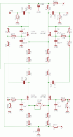
The 3rd order LP is a different story and it took me quite some time to figure out a possible solution that is shown in the schematics below. I was inspired by a paper that I found on Texas Instrument's website. There I also found a piece of software called "FilterPro" that I used to calculate component values for this (what they call) Multiple Feedback (MFB) topology.
To be honest, I have no clue if this works. The Spice simulation looks very promising but I want to ask what you guys think. Am I on the right way?
Attachments
3rd order low pass
I am currently using a 1st order high pass with my Aleph P 1.7. It is the same method as you are suggesting by using a 0.47uF blocking cap. I used this same method with my BZLS prior to making the Aleph.
This signal then goes to the high pass amp.
The 2nd order low pass is achieved via passing the high pass signal to op amps (Burr Brown OPA132). This signal then goes to the low pass amp.
Your circuit design seems to only show one output which I asume is the low pass.
How do achieve the high pass using this circuit?
Are you planning to build two BZLS one for high pass and one for low pass?
I am very interested in your circuit.
Ignatz: You are right, my schematic only shows the low pass section. I omitted the high pass "channel" because it's pretty straight forward and I have already built it some time ago. This way I could replace 3 * 33uF (in parallel) of the passive crossover by a small 0.22uF high quality cap on the BZLS output...
Nelson: Yes, I simply forgot them. Thank's for mentioning!
Nelson: Yes, I simply forgot them. Thank's for mentioning!
superstition
If you are going to use 1 BZLS for high pass and 1 BZLS for low pass you must be placing your attenuator on the inputs or you have attenuators for outputs of both high and low pass.
Also what type of 3rd order filter did you design; Butterworth, Linkwitz Riley, Chebyshev, Sallen Key etc. What is the phase angle between the outputs at the cross over frequency?
Ignatz
Placing the attenuator on the output requires a four gang pot/resistor switch or whatever because there are four independent channels. Attenuating the input only needs two. Much more important is the requirement given by the high pass filter that is set by the output caps. You need a constant output impedance otherwise your crossover frequency varies with attenuation. In fact I don't know if it's possible to attenuate the output over the desired range without changing output resistance. At least I doubt.
In short: I'm placing the attenuator on the input. I decided to use Sowter 9395 Attenuator Transformers (see http://www.sowter.co.uk/attens.htm and http://www.geocities.com/agalavotti/Tvc.html for more information). They have three different primary taps to alter gain. I will try to setup the whole thing in a way that I don't need much attenuation at all for normal listening conditions.
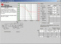
To your second question: It's a Butterworth filter in a (what TI calls) Multiple Feedback configuration. Phase angle at 100Hz is -135 degrees. See the attached image more data.
Attachments
superstition
Thanks for the information regarding the attenuation transformers. This is the first time I have seen a transformer used for this function.
My attenuator is on the output and it does not sound like it affects the Fc.
I think the single resistor simply nulls out a portion of the difference in the output signal. It simply partially shorts the + to the -.
The reisitance to ground of the outputs ranges from 5K5 with attenuator full clockwise and 5K0 attenuator full counter clockwise (measured) with amp connected.
Which converts to Fc of 116 Hz and 127 Hz (calculated) respectively. The delta of 11 Hz max seems to be of no consequence although now I wish I could measure the frequency to be sure.
I put an LC filter in front of the BOSOZ (used single ended) and used one channel for high and one channel for low. For stereo, this takes two BOSOZ's which I powered off of one large power supply. I used a 10K stepped attenuator in front of the filter for volume control.(This is probebly not the best spot as the attenuator is probebly affecting the crossover frequency.)
I use the gain controls that Nelson built into the circuits for balance between high and low as well as left and right channels. (I noticed that if I turn these gain controls quickly, the cones on the drivers will push out or pull in while I am turning the pot. I may have burnt out the tweeters this way).
The main amps are Aleph 30's...and it all sounds pretty good to me...
- Status
- This old topic is closed. If you want to reopen this topic, contact a moderator using the "Report Post" button.
- Home
- Amplifiers
- Pass Labs
- Balanced Zen Line Stage X-Over


 .
. 
