Mad_K said:Will this schematic make everybody happy? (Including my PSRR)")
Yes, I consider it as an improvement.
I would be even more happy
if you numbered your versions of PDF.OTA-3.5.1.pdf
OTA-3.5.2.pdf
OTA-3.5.3.pdf
..... or whatever you wish to call your versions
Makes it easier when I download and save your documents.
lineup said:
I would be even more happy
OTA-3.5.1.pdf
OTA-3.5.2.pdf
OTA-3.5.3.pdf
..... or whatever you wish to call your versions
Maybe MKI...MKII....and MK SE (Special Edition )...
Hi guys !
This post seems nice !
I have built one PF 99 and one personal design really close to OTA but with an op amp in voltage gain, both sounded really nice to my ears !
I will probably make a bigger amp in this style (mosfet SE).
Current source will be probably some LM317s or 350 ...
PS : for those who want to laugh, some of my experiments :
http://www.ptsoundlab.com/forum/viewtopic.php?t=3442
darkfenriz said:
Jorge, Lineup
C2 keeps the input at constant potential against ground (in original design), if -V rises by 1V, then voltage at gate stays still
Yes..but the source voltage is raised by 1 volt and if the gate stay stiil, the mosfet gate source have changed 1 Volt and this 1 volt will appear at the output (as noise).
The last change is virtually nothing.
A little step for man...a great step for the mankind ...
darkfenriz said:The last change is virtually nothing.
Jorge, Lineup
C2 keeps the input at constant potential against ground (in original design), if -V rises by 1V, then voltage at gate stays still.
Have you been had by source follower?
regards
And that 1 Volt rise.
In the output. Where MOSFET and Resistor is the divider.
Will it add 1 Volt across Resistor or across MOSFET?
Because surely there will be an 1 Volt increase somewhere.
And best is if load output is taken across the part of output
where that 1 Volt is not added.
My guess is that if Gate stays at same potential (filtered by electrolyt lowpass filter)
the Source stays at same potential
but any ripple or supply AC voltage change will be across Drain-Source of MOSFET.
And if output is taken across MOSFET
any supply AC change within audio frequency will also be transmitted to LOAD.
After a good nights sleep I'm even more happy. Starting to agree with you on the PSRR guys. I will rename it when it changes revision (in my book). I'll do a PCB that fits into the place of my active design, have a listen, then I'll snap some pictures and we can have some more of this enlightenling conversation. Good to see the PSRR of this thread has gotten better BTW
And that 1 Volt rise.
In the output. Where MOSFET and Resistor is the divider.
Will it add 1 Volt across Resistor or across MOSFET?
Because surely there will be an 1 Volt increase somewhere.
Resitor has 5 ohms, hexfet's source at ~2A probaly 5 siemens. Ratio=25 times=28dB=not_that_bad
If I miss something please be patient and nice and explain me, because I hate things I don't understand.
BEST REGARDS
I missed something in the first version, darkfenriz.
That the C2 capacitor was attached to GND, not to -22.5V, which I thought.
This means you are right. It does not change much with new version.
--------------------
But still there is a slight improvement with new version.
As in the first version AC supply ripple will appear across Power Resistor
there will be a AC current ripple in this resistor,
and when current changes in MOSFET,
this means small Gate-Source voltage changes.
This voltage change will be across the LOAD, if LOAD is taken across FET.
In new version, if supply ripple, there will be no change in Resistor and MOSFET Current,
so, Gate-Source voltage will be constant (almost).
There will be a change only in Drain-Source voltage
and Gate potential will be constant.
-------------------------------------
I am sorry I did not read the first schematic, good enough.
You did, and so you had a valid point!
darkfenriz said:
Resitor has 5 ohms, hexfet's source at ~2A probaly 5 siemens. Ratio=25 times=28dB=not_that_bad
Darkfenriz , think that in the first grounding arrangement , you have a resistance of 5 Ohms between your signal , referenced to one rail and the other (noisy ) voltage rail....in the SE (special edition version...
) you have a very high impedance ( near a CCS , the Mosfet intrinsic drain resistance ) between the signal reference and the other voltage rail...If I miss something please be patient and nice and explain me, because I hate things I don't understand.
Good to you!...

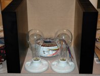
bob_v5 said:hi. on the sewa amp that this thread spawned from the is a circuit with a light bulb instead of a resistor. Does any one know what type to use?http://www.diyaudio.com/forums/showthread.php?s=&threadid=66822&highlight=
Not shure, but Nelson talks about them in his Zenlite article. He used 300W Sylvania bulbs from www.mcmaster.com I'm shure he'll dig up som part numbers if you ask him
McMaster-Carr #s:
Porcelain Light Bulb Socket
300W Clear Light Bulb
...maybe order an extra porcelain socket, cause they didn't do such a
great job packing and one of mine showed up shattered. You can do
a return, but the cost equals just buying another one
Porcelain Light Bulb Socket
300W Clear Light Bulb
...maybe order an extra porcelain socket, cause they didn't do such a
great job packing and one of mine showed up shattered. You can do
a return, but the cost equals just buying another one
Attachments
moe29 said:...maybe order an extra porcelain socket, cause they didn't do such a great job packing and one of mine showed up shattered.
They're some strange ones there at McMaster-Carr. Recently I ordered just two pieces of paper/phenolic rod, each was about 5/8" in diameter and 48" long.
I swear to God they arrived in a box that was 3 feet wide, 4 feet long and 1 foot deep.
se
Nelson Pass said:If you can't find it at Digikey or Mouser, you can bet that
McMaster-Carr has it.
Got that right.
And just yesterday I was finally blessed with an actual hardcopy McMaster-Carr catalog. 3,664 pages baby! All on premium grade paper. Not that newsprint c_r_a_p you get with the Mouser and Digi-Key catalogs. Weighs about 10 pounds.
Nothing like curling up in a nice comfy chair flipping through a real catalog, coming across all sorts of cool stuff you never knew existed.
Life is good.
se
Tube_Dude said:
Darkfenriz , think that in the first grounding arrangement , you have a resistance of 5 Ohms between your signal , referenced to one rail and the other (noisy ) voltage rail....in the SE (special edition version...
Agreed, but that's not that tragic with proper star ground I think.
But still, you are right, SE is better.
darkfenriz said:
Agreed, but that's not that tragic with proper star ground I think.
But still, you are right, SE is better.
The star ground don't have nothing to do with it , after all ,is in the AC diference between the power rails , that is the problem.
But if instead the 5 Ohms resistor , you use a CCS , the problem diminish...but it's still better the SE arrangement.
Cheers
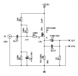
For anyone
who wants to know what we are discussing:
Here is newest version of OTA - One Transistor Amplifier by Mad_K
See my attchament here below.
Mad_K has posted PDF schematics of amplifier and power supply
in Post37 and Post38
...........................................
- This amplifier works in Single End Class A.
- There is no voltage gain.
- There is a lot of current gain.
Attachments
- Status
- This old topic is closed. If you want to reopen this topic, contact a moderator using the "Report Post" button.
- Home
- Amplifiers
- Pass Labs
- OTA - One Transistor Amplifier