Since people are going ahead on purchasing the Lovoltech
power JFETs, I thought I would share some of my matching
data.
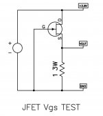
It's quite simple, as seen from the circuit. A measurement of
the Vgs under identical conditions is adequate for most
applications. The value is useful for creating differential pairs,
and in cascoded single-ended applications becomes valuable
when selecting a Source resistor to ground.
In the case of selecting a Source-to-ground resistor, the value
of the resistance can be used to set up the optimal load line
for the lowest distortion.
power JFETs, I thought I would share some of my matching
data.
It's quite simple, as seen from the circuit. A measurement of
the Vgs under identical conditions is adequate for most
applications. The value is useful for creating differential pairs,
and in cascoded single-ended applications becomes valuable
when selecting a Source resistor to ground.
In the case of selecting a Source-to-ground resistor, the value
of the resistance can be used to set up the optimal load line
for the lowest distortion.
Attachments
Depending on all the other usual factors, optimizing the
Source resistance in a cascoded single-ended system can
improve the performance quite a bit. Your results will vary
somewhat, and so for a given circuit design, it is necessary
to test to find the optimal values, but here is an example
of a distortion curve in an arbitrary system where the cascode
has a grounded Gate. One curve shows the untrimmed value
of Source resistance, and the other has been adjusted slightly.
Attachments
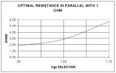
For this same circuit, here is a curve of optimal resistance
values for a range of Vgs values. Again, this is simply an
example of a single design, and these values should not be
applied in general. For a given design, there will likely be a curve
which resembles this in principle which will obtained by actual
testing.
values for a range of Vgs values. Again, this is simply an
example of a single design, and these values should not be
applied in general. For a given design, there will likely be a curve
which resembles this in principle which will obtained by actual
testing.
Attachments
same to you and your folksNelson Pass said:Happy New Year.

and many more-spent in good health and fun
hehe
same wishes to any DIYer around

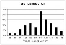
one thing which never ceases to amaze me is that when I match a couple hundred HexFET's or Lateral MOSFET's I always get a bimodal distribution of values -- even when they come in a case of 300 or 360 devices, at least for IRF and Renesas products. I wonder what kind of "titration" is done during the manufacturing process to "effect" this distribution. From a "mean-variance" standpoint it would make the distribution look quite good, but when you do a histogram (a la NP) the utility of matching stands out.Nelson Pass said:Here's a distribution of values of the population of a couple
of tubes:
Of course, if you use a bigger hammer the bimodality goes away.
Confessions of a parts matcher.
I like the numbers to sit still long enough for my eye to focus on them. Since others will soon be attempting to match these Lovoltech JFETs, I thought I'd share a secret: There's an art to this matching thing.
The trick is in the heatsink. No heatsink at all leaves the numbers ascending as the temperature rises. You're asking something the size of your pinky fingernail to dissipate about 2W. The temperature climbs rapidly. It doesn't take long before your fingers start warning you that you're holding something hot and you need to put it down Right Now. This is a serious distraction when you're trying to concentrate on reading a bunch of flickering LEDs.
On the other hand, too large a heatsink dissipates heat too well. You're throwing heat into a black hole. It's better than no heatsink at all, but I've got a better solution.
Shhh...lean close, 'cause I'm about to tell you the secret.
Get a heatsink that will stabilize at about body temperature with Pd=2W. That way it's comfortable to handle and your body heat won't throw off the readings.
I'm sure that Nelson long ago built an elaborate box that sits on a table and handles everything. But then he matches more devices than all of us put together and it's worth his time to build such a device.
I'm generally working in smaller batches and it's only an occasional thing. I can't spare the space to park a dedicated parts matcher, either. So I'm left cobbling something together every time I need to match devices. Now, as many of you know, I'm embroiled in matching a gazillion LU1014D at the moment. Fair enough. But how to do it?
To begin with, most folks are going to want parts that are matched "the way Nelson does it." So the schematic Nelsons gave earlier in the thread is what I'm using. It's simple enough. Dial in the voltage on the power supply. Hook a meter across the 1 Ohm resistor and...oops...forgot the heatsink.
Thus ensued a Goldilocks too-hot-or-too-cold search for the right heatsink. I'll cut to the chase and say that the "just right" heatsink for this job turned out to be a flat piece of scrap 1/8" aluminum about 1 1/2" by 3". The precise dimensions aren't going to be that critical, but I'll measure it if anyone cares to know the actual size. In fact, I almost think it would be better if it were a little smaller. Be that as it may, with the right heatsink the JFETs settle down within about 3 to 5 seconds. The heat they deliver to the heatsink makes it comfortably warm to hold.
Goldilocks is now very happy with her porridge.
She can find her own bed. She's too young for me.
Besides, I prefer brunettes.
Grey
GRollins said:Confessions of a parts matcher.
The trick is in the heatsink. No heatsink at all leaves the numbers ascending as the temperature rises.
I suppose that NP has a device which clamps the MOSFET or JFET into a jig with heat sink attached.
If you match devices at different ambient temperatures you'll find that the absolute values will change, but that the relative values remain pretty much the same -- right now it's probably about 64 degrees F in the lab -- in the summer it will get up to the mid 70's --
fwiw -- I use a constant current source -- using a TEK PS5010 power supply bought on the cheap when the internet bubble had crested -- you can do the same thing with an LM317 and a resistor from the adjust pin to the output --
I do a straight-forward way of matching.
I build the amp I¡¯m going to use.
Heat them up, and check Vgs of mosfets one by one.
Change mismatching mosfets.
Finally solder all closely matching mosfets.
It is an easy work when I build single stage amp (by p2p).
I usually spend, e.g. 25 stones (in one plastic container) to get 8
with only 32% efficiency. The efficiency is low, maybe too low . . .
So, to improve the low efficiency, I use remaining mosfets
where the matching is not required.
My F1 is built in that way.
I hope this info will be of help for the F-club members.
Regards
jh
I received 25 unmatched Lovoltech 1014 N-channel Jfets from Grey Rollins and thought I would share my matching numbers.
The test setup is as Nelson described. 3 volt supply, 1 ohm source resistor. The Jfets Vgs ranged from 0.97 to 1.22. Out of the 25 units 28% fell in the 1.17 to 1.19 Vgs range, another 20% fell into the 1.11 to 1.13 range. Plenty of matches.
BDP
The test setup is as Nelson described. 3 volt supply, 1 ohm source resistor. The Jfets Vgs ranged from 0.97 to 1.22. Out of the 25 units 28% fell in the 1.17 to 1.19 Vgs range, another 20% fell into the 1.11 to 1.13 range. Plenty of matches.
BDP
We aren't necessarily looking for matches, as the initial application
is 1 per channel, but it is nice to match any given pair of channels.
In ZV9, the Vgs figure we get helps to set the Source resistance
to an optimal value, although the criterion for optimal here is
lowest distortion at 1 watt.
is 1 per channel, but it is nice to match any given pair of channels.
In ZV9, the Vgs figure we get helps to set the Source resistance
to an optimal value, although the criterion for optimal here is
lowest distortion at 1 watt.
- Status
- This old topic is closed. If you want to reopen this topic, contact a moderator using the "Report Post" button.
- Home
- Amplifiers
- Pass Labs
- JFET matching