It's a very nice circuit.
Thank you very much 2 picoDumbs for your interest.
xrk971 has already built it and liked it a lot.
The greatest of all regards.
Thank you very much 2 picoDumbs for your interest.
xrk971 has already built it and liked it a lot.
The greatest of all regards.
Yes, one of the lowest distortion Class A amps I have built. I like that no exotic matched JFETs are needed and amp costs maybe $8 to build. Having a variable dial-a-harmonic profile feature is great too.
Fantastic and original design by Diegomj1973.
Last edited:
The original circuit runs at about 80 watts per channel (40V x 2 amps).
I like to see a transformer rated at least twice that and preferrably 3 times.
So for mono, preferred transformer is 240 VA, minimum 160 VA
Stereo, 500 VA, 300 VA.
Thank you Mr.Nelson,
one last query. In my local store below parts available. What are the best replacement parts for Q1,Q2 & Q3 transistors.
Mosfets
Vishay IRF530 100V 14 Amp N-Channel MOSFET
Vishay IRF540 100V 28 Amp N-Channel MOSFET
Vishay IRF740 400V 10 Amp N-Channel MOSFET
Vishay IRF840 500V 8 Amp N-Channel MOSFET
Vishay IRF840 500V 8 Amp N-Channel MOSFET
Vishay IRFP150 100V 41 Amp N-Channel MOSFET
Vishay IRFP240 200V 20 Amp N-Channel MOSFET
Vishay IRFP250 200V 30 Amp N-Channel MOSFET
Vishay IRFP260 200V 46 Amp N-Channel MOSFET
Vishay IRFP264 250V 38 Amp N-Channel MOSFET
Vishay IRFP460 500V 20 Amp N-Channel MOSFET
Lateral Mosfets
EXICON ECX10N20 200V 8A 125W N-Channel Lateral Mosfet
₹ 470.00 INR
EXICON ECW20N20 200V 16A 250W N-Channel Lateral Mosfet
₹ 870.00 INR
Thanks.
Please open the datasheets and compare forward transconductance (gfs), gate threshold voltage (Vgsth), input capacitance (Ciss), reverse transfer capacitance (Crss), junction to case thermal resistance (RθJC) and case to sink thermal resistance (RθCS) to better understand what 2pico is trying to tell you and Pass design in general. We will help you in doing so and you will have better executed build. Choosing parts wildly will cost you a lot in terms of quality, reliability, time and money.Ok got it from another thread . . . .
P = I ^2 * R
Same current to different resistance leads to different dissipation.
Correct.
I mean P1 & P2 5watt and R4 & R6 3 watt.
As Papa state in his PLH pdf, he calls 3W only for R4, R8 and R9. P2 can be 2 - 5W type, higher is better.
P1 is regular trimpot, a sealed Bourns multiturn will make output offset adjustment easier.
Why? Because when P2 is fully cw, R4 will see the full AC output signal, R6 and P1 will only see the 12mA bias. When P2 is in the mid position it will also see part of AC output signal, a bigger wattage has more robust wiper.
I think the 3W need of R8 and R9 is clear.
Last edited:
P1 and P2 are specified as 5W. That means they are NOT
these sealed multi-turn are usually 500mW (0.5W)
A 500ohms 0.5W trim pot has a maximum current rating of sqrt(0.5/500)= 31.6mAdc
For reliable life de-rate to <20mApk, (1/2power) and for reliable long term use, de-rate to <16mApk, (1/4power).
Is it possible the spec has a typo?
Could the 5W rating for P1, P2 & P3 really be 0.5W?
Is this a case of a lazy typer omitting the leading zero from a value less than 1?
What do we do to charge up C5?
It will over load both R6 & P1 at start up/Power ON.
regular trimpot, a sealed Bourns multiturn
these sealed multi-turn are usually 500mW (0.5W)
A 500ohms 0.5W trim pot has a maximum current rating of sqrt(0.5/500)= 31.6mAdc
For reliable life de-rate to <20mApk, (1/2power) and for reliable long term use, de-rate to <16mApk, (1/4power).
Is it possible the spec has a typo?
Could the 5W rating for P1, P2 & P3 really be 0.5W?
Is this a case of a lazy typer omitting the leading zero from a value less than 1?
What do we do to charge up C5?
It will over load both R6 & P1 at start up/Power ON.
Last edited:
Sorry another mistake, P1 is bias adjustment.... P1 is regular trimpot... output offset adjustment easier....
I never see Mr. Pass specify 5W P1 in his PLH article. Who did?P1 and P2 are specified as 5W. ...
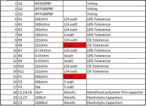
Quote from PLH article: "Most of the resistors are ¼ watt types, but I recommend a 3 watt value for R4 and R8 and R9. The capacitors are all rated at 50 volts. None of the values needs tight tolerance. P2 is best chosen as higher wattage type. You can get by with 2 watts, but 5 watts is preferred."
If you are worried, maybe you want to check turn on transient in spice with intended power supply, I never found any mistake in Mr. Pass article left uncorrected....What do we do to charge up C5? It will over load both R6 & P1 at start up/Power ON.
It is rainy day today...
I was reading about SIT-3, then I bumped onto an old article about JLH amp, then I remembered the PLH, read it again, then...
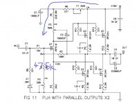
I was just wondering, is it possible to build a PLH, but with SIT-3 front (buffer+transformer) instead of Q1 (Irf610 mosfet)?")
I was reading about SIT-3, then I bumped onto an old article about JLH amp, then I remembered the PLH, read it again, then...
I was just wondering, is it possible to build a PLH, but with SIT-3 front (buffer+transformer) instead of Q1 (Irf610 mosfet)?

- Status
- This old topic is closed. If you want to reopen this topic, contact a moderator using the "Report Post" button.
- Home
- Amplifiers
- Pass Labs
- Plh