Goodevening.
I.ve got a problem with my aleph 5. I build it up, got 12v from the + and 12v from the - from the bridgerectifier to two mono psu's, with each 2 BC47000 uF elco's, from the left I got at the + 9,5v
at the - 24v, from the right channel i got at the + 2,6v and at the -32,8v. Not anything from + - 34v, so what is happening? I got 2 tranny's from 300VA 2x25volt.
He Hugo thanks for replying!
I am going to bed and will reply tomorrow.
Good night Teake.
I.am not that good in this so it will be difficult to tell you wat I did.
I have two bridgerectifiers and have taken the wires with the same colors together from the trannies, putting two on the left and two on the right on the rectifier. The two elkos per channel I took the + to the rectifierbridge and the - ,and between them i have taken a little copper bridge connected between the + and - , solderded a connector on it with a wire to floating ground. It lookes like the one PedroPo used in his aleph5
aleph5 psu
Hello!
2 trannys, 300VA 2x25v 6A, with each 2 primary wires to main and 4 secundairies, red, yellow, grey and blue. I connected the 4. so i got 2 red, 2 yellow, 2 grey and 2 blue, to the rectifiers ac points. The rectifiers are 25A/400V. Than i connected + and - from the rectifier to the elko's and a wire to ground from both seperate psu's. On the 4 elko's i got on each of them a solen bypass capacitor from 1.00uFJ, 400v.
Attachments
intense-tavda said:Thanks Magura
So I need 4 bridgerectifiers instead of 2, but I only can get 35A/600v here in my town can I put them next to my other rectifiers, or do I by 4 35A/600 and what will be the best. Thanks Teake.
All 4 of the same kind would be nice but not necessary. Attached is how you should wire them up. Couldnt really see you pic.
Attachments
Hi,
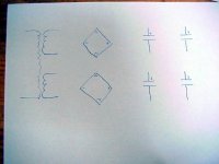
Just to be complete, I added a picture to make two mono supplies using two bridges.
I have to say I myself would use four bridges, although this picture is a double power supply from the original from Mr. Pass himself, and I did not hear any difference between two bridges and one in my Aleph 5.
If you are planning to use only four capacitors, you could also think about using a CLC solution, with two secondaries parallel, but you would loose the mono aspect.
Remember, 4 bridges generate a lot of heat, so take care how to mount them!
Greetings, Harry.
Attachments
intense-tavda said:Is this for one channel?
Hi intense-tavda,
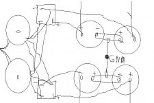
No, this is for two mono PSU's as you specified in the first mail.
The four red circles are the two voltage (+ and -) outputs for every channel, the two missing zero's (0) are meant to be on the thick green bar. This represents the central zero of the amp.
When you would use four rectifiers, the drawing changes ofcourse. then you get twice the drawing as show in the first mail in this thread:
http://www.diyaudio.com/forums/showthread.php?s=&threadid=62592
(I build one myself based on this design)
Greetings, Harry
Thanks Harry!
But I did it the Nelson way and the difference between the + and - rail was very big. Something like 25V. Only I connected the 4 wires together from both trannies wich I connected to the rectifiers. so each trannie has 4 secundairies, wich one should I connect. Is it possible that I destroyed the rectifiers?
But I did it the Nelson way and the difference between the + and - rail was very big. Something like 25V. Only I connected the 4 wires together from both trannies wich I connected to the rectifiers. so each trannie has 4 secundairies, wich one should I connect. Is it possible that I destroyed the rectifiers?
intense-tavda said:I,ve got a red, blye, yellow and grey wire, wich ones ar for the GND? Someone can tellme? Thanks!
Hi intense-tavda,
I blew up my rectifiers when I connected my trannie wrong. I connected the wrong pair together, and actually shorted the tranny over the two rectifiers!
Where did you get your tranny? As you are dutch, chances are that you have an Amplimo. The colours match.
Check this: 300 VA Amplimo If this is the same, connect yellow and blue to central zero. Red and grey go to the rectifier.
You can also measure (CAREFULLY) between all these wires. When you select a wrong pair, you get about the same value on the pairs or zero.
When you select the right pairs, you get exactly the same values (25A).
DO NOT SHORTEN WHEN MEASURING

When you have the right pairs, it does not matter which one you connect to the central zero.
Greetings,
Harry
You cannot connect four wires from two different trannys to the rectifier. The trick is to connect the central connections to the zero instead of the rectifier.
Even if you connect the correct phases, you still only bring one floating voltage over the two capacitors. The plus and minus voltage resulting would then be defined by the internal ohm value of the capacitors. And these are very small.
This is why Nelson uses two voltages, and couples them together over the central zero. This way the plus and minus are equidistance to the central zero point.
When you would use four bridges, you get four floating voltages, that are only connected to ground.
Greetings,
Harry.
Hi there!
I connected the blue and the yellow together, from each trannie apart, but did not connected them to ground, doe I have to do that? Or can I leave it this way? I left the amplifier on for about 2 ours and get now for one channel + 32,6v and - 41,4v, for the other channel - 40,6 and + 33,1, where does te difference come from? I will check it tomorrow.
I connected the blue and the yellow together, from each trannie apart, but did not connected them to ground, doe I have to do that? Or can I leave it this way? I left the amplifier on for about 2 ours and get now for one channel + 32,6v and - 41,4v, for the other channel - 40,6 and + 33,1, where does te difference come from? I will check it tomorrow.
Hi intense-tavda
Check mail 15.
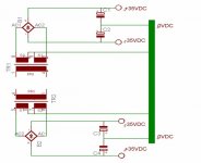
When you do not connect the central wires to zero, you create one floating voltage of 75 volts. This voltage is divided over the two capacitors because of resistor values of the capacitors and the connecting bolts.
When you connect the central wires to zero, you create two voltages around one central voltage. When you tie this one to zero, you get what you want.
I tried to make the connections clearer on the schematics.
Disconnect the capacitors, and measure between the outputs of the rectifier and the two connected wires from the trannies. These values should be the same.
Happy Hunting, Harry.
Check mail 15.
When you do not connect the central wires to zero, you create one floating voltage of 75 volts. This voltage is divided over the two capacitors because of resistor values of the capacitors and the connecting bolts.
When you connect the central wires to zero, you create two voltages around one central voltage. When you tie this one to zero, you get what you want.
I tried to make the connections clearer on the schematics.
Disconnect the capacitors, and measure between the outputs of the rectifier and the two connected wires from the trannies. These values should be the same.
Happy Hunting, Harry.
Attachments
He Harryeng
I did what you and master told me, i put the wires to ground zero, but there is still some difference between left en right and + and -, for left there is -39,7V +36,8V, for right there is -39,2V and + 36,5V, so what is happening here? Should it be exactly 34 for - and 34 for +? Teake.
I did what you and master told me, i put the wires to ground zero, but there is still some difference between left en right and + and -, for left there is -39,7V +36,8V, for right there is -39,2V and + 36,5V, so what is happening here? Should it be exactly 34 for - and 34 for +? Teake.
Strange, 
Something is not right. Maybe the rectifier or the elco are blown? You are measuring without a load i presume?
I would disconnect the elco's and measure directly between the rectifier output and zero. When these still give a difference, measure the rectifier input and zero (=tranny output).
This should give you a clue about where to look. The plus and minus side of all these measurements should give identical values.
Greetings, Harry.
- Status
- This old topic is closed. If you want to reopen this topic, contact a moderator using the "Report Post" button.
- Home
- Amplifiers
- Pass Labs
- aleph 5