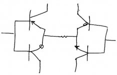
Is this Idea a valid option worth trying?
Improved linearity through complementary differential further tamed with sort of double-x?
Or would the circuit blow and explode due to the different charges meeting at the gates?
Just a silly morning-idea before coffee & work?
yours,
Rüdiger
Improved linearity through complementary differential further tamed with sort of double-x?
Or would the circuit blow and explode due to the different charges meeting at the gates?
An externally hosted image should be here but it was not working when we last tested it.
Just a silly morning-idea before coffee & work?
yours,
Rüdiger
Have a look at some of John Curl's designs as far back as the '70s and you'll see the same thing. Others seem to know it as a 'diamond differential' and I believe there's yet another name for it, but I can't remember what it is at the moment. I tend to think of it as John's, since that's where I saw it first, but I don't actually know who came first.
Yes, it will work for X circuits, although existing JFETs don't have a very great voltage range, so be prepared to cascode if you want more than a few volts of output.
Grey
EDIT: Caps in the feedback loops will take care of DC problems.
Yes, it will work for X circuits, although existing JFETs don't have a very great voltage range, so be prepared to cascode if you want more than a few volts of output.
Grey
EDIT: Caps in the feedback loops will take care of DC problems.
Actually, it looks very much like the X (not XA) front end. I believe,
though, that the diamond differential front end was a design
by Sansui to get very high slew rates. I have not seen it in
a product since, but perhaps people are applying the name to
what I would refer to as Curl's JFET dual differential. It seems
to me that dual differentials had already been invented, but
John used the Vgs character of the JFETs to self-bias very
elegantly, much as you might see in tubes, but symmetric with
P and N channel devices.
John posted here on the history/taxonomy of the circuit some months back, but I'm not in the mood to argue with the search engine to try to find it. For some reason they frown on alcohol here at work and I refuse to wrestle with the search function without something liquid to sustain me.
From memory: I think he said he came up with the idea at Ampex(?) in the late '60s. Someone else came up with the same general thing at about the same time. The Sansui version was in the mid-to-late '70s; they drew it differently, but it boiled down to the same thing. If someone knows where John's post is, it would be better to rely on his rendition rather than my recollection of his post.
At any rate, you can go to www.marklev.com and look at the schematics of the JC-2, where he used it in the line stage.
I've played with the circuit with excellent results and I'm sure that Nelson has flogged it within an inch of its capabilities for the X amps. I believe Nelson cascodes his JFETs with bipolars, presumably Zetex parts.
Grey
I do indeed.
But with regard to the Diamond Differential, I don't recall the
exact schematic, but it is designed to kick in with lots of
additonal current beyond the bias point. It never achieved
popularity, I beleive because its sole purpose was to beat
the **** out a single spec - slew rate, which I regard as a
red herring.
(insert slew rate rant here)
JC's differential circuit was a model of subtlety and simplicity
by contrast, and lives on as a classic.
BTW, I did generate a bunch of performance curves on a circuit
like the one that started this thread. I'll dig them up.
finally, a question for which I remember the answer
the link grey refers to is here:
http://www.diyaudio.com/forums/showthread.php?s=&threadid=22455&highlight=
mlloyd1
who is looking forward to seeing nelson's curves
hmmm, that didn't come out right did it?
the link grey refers to is here:
http://www.diyaudio.com/forums/showthread.php?s=&threadid=22455&highlight=
mlloyd1
who is looking forward to seeing nelson's curves
hmmm, that didn't come out right did it?
GRollins said:John posted here on the history/taxonomy of the circuit some months back, but I'm not in the mood to argue with the search engine to try to find it. ...
Grey
Hi,
Would be great to have that performance curves!
My question arouse when i was looking at the borbely circuits and was thinking of a way to make them 'real balanced' (apart from simply doubling them). Since those are (often) feedbacked via the '-' input node I recalled the 'x'-thing and re-read the zen/susy paper instead of a late night crime-fiction
If it all fits, I might use it as a second stage in a phono amp (after a passive network), so apart from very good linearity it is interesting how big the input voltage range is and how immune to complex input 'loads' (I don't know how to say that better).
But apart from my intention I'm eager to follow your input,
thanks,
Rüdiger
Here we go. This is the same circuit, with 8 mA total
bias, 2.2 Kohm Drain resistors, and +/- 30 volt rails.
The open loop gain is 50, the CMRR is -100 dB, and two
curves are shown, but I forget what condition change there
was - my notes make vague reference to 6 mA bias also,
and that might be the difference, but more likely is a different
load resistance.
Attachments
Hmmm...the post mlloyd1 linked to is half of the stuff I remember, but not all. I seem to recall John discussing the 'diamond' circuit as well. Must have been a different post in a different thread.
I don't have a schematic of the diamond circuit at hand, so I'll take Nelson's word for it that it had extra current add-ons. He's in a better position to judge these things than I am, as he seems to have schematics for everything ever made.
Nelson, are those curves for the 389/109? If so, isn't 30V a little hot for the 109, or is the part more durable than the spec sheets would have you believe? If I recall, the 109 is a 25V part, which is wierd considering that the 389 is 40 or 50V according to the sheets I've got here (buried somewhere under all the other stuff...).
Grey
Yes, those were 389's and 109's.
I think the "diamond" topology is more like this diagram, where
you see the diff pairs operating push pull without limitation to
the potential current they can deliver - they are biased at
the Gates, not single-ended, and could operate class AB
beyond the bias point. This allows for the current to deliver
enormous slew rates.
Attachments
Onvinyl said:Is this Idea a valid option worth trying?
Improved linearity through complementary differential further tamed with sort of double-x?
Or would the circuit blow and explode due to the different charges meeting at the gates?
An externally hosted image should be here but it was not working when we last tested it.
Just a silly morning-idea before coffee & work?
yours,
Rüdiger
Have a look here:
http://www.diyaudio.com/forums/showthread.php?postid=613823#post613823
Regards
Adam
Nelson,
I see the schematic you drew as being the same as John's, just with Rs=0; i.e. each device running at Idss, which ain't that far a stretch, given that the biasing resistor is usually pretty small, anyway.
Note that all bets are off if I'm mis-remembering the diamond circuit topology. For some reason, I'm thinking that I saw it drawn with the connections criss-crossed between the two differentials...probably just to confuse the issue.
As I said, I regard it as being "John's circuit" regardless of other versions. One of these days I'm gonna buy me a JC-2 (regardless of phono EQ errors). I think the circuit's elegant and I like the way they look. So sue me.
Your and John's pinky fingers know more than I will ever know about electronics, but that doesn't stop me from thinking the circuits are cool. Actually, come to think of it, I've got a complementary differential in the tweeter section of my current active crossover. Thanks, John.
Grey
i really like complimentary jfet input stages too, just seems too elegant to not use! the thing that really burns my britches is the matching. i don't sleep well now because i measured the gains of my upper and lower diff amps of my Servo 50 years ago when I was building it. even though the jfets IDSS matched, transconductance clearly didn't, so the gains were slighty different (yeah, yeah, my wife calls me a nerd, too). that can't do anything nice to my distortion spectrum once I wrap global NFB around the amp.
what can i say, it's a complementary input stage, i want complements, d@mmit
mlloyd1
what can i say, it's a complementary input stage, i want complements, d@mmit
mlloyd1
GRollins said:I see the schematic you drew as being the same as John's, just with Rs=0; i.e. each device running at Idss, which ain't that far a stretch, given that the biasing resistor is usually pretty small, anyway.
First you will note that I drew a bipolar circuit (upside down).
It seems to me that John's contribution consisted of the self-
biasing of JFET dual differentials, not the notion of dual
differentials as such. I can only go by the apparent 1974 release
of the JC-2, and unless I am mistaken, the notion of dual
differentials precedes that. If I am mistaken, perhaps John will
comment.
Such amplifiers as the Daniel Myers 'saurus amps and Jim
Bongiorno's Ampzilla used dual differentials also, but you will
note that in those cases the circuits were CCS biased. This
means that they did not slip into a Class AB mode so as to
provide more than the bias current.
John did not intend such operation, as it is highly non-linear,
and Sansui may have tarted it up for the occasion, but you'll
recall that this was during the "slew-rate wars" of the 70's.
Regardless of the details, the basic concept of the diamond
differential (the not-the-Curl circuit) remains the same, but it's
only value seems to have been for high slew rate numbers -
running an input device in Class AB is not a popular approach.
If I remember correctly also Yamaha made an amplifier with a dual differential input, each differential having its own current source like all the others do. So far nothing special.
The special thing is that they connected a big capacitor between the common emitters of both differentials (could have been common sources too, I don't know). Now you get the same class AB characteristics as mentioned above, to get really high slew rate specs. The charging current of the next Miller cap is not limited anymore to the value of the current sources. The capacitor allows for shifted DC biasing.
Steven
Nelson,
Mea culpa on the bipolars above. What with Olivia wanting to sit in my lap and my wife requesting that I fetch a bottle of wine for supper, my mind just interpreted them as active devices in the generic sense. My focus was on the hookup between the two differentials, not the differentials themselves.
I already had the John/JFET connection, just didn't look at your schematic closely enough.
Grey
Clearly, I wasn't...not enough, anyway. (Note my reference to Idss etc. above. Sigh.)
Like the Shadow, wine has the power to cloud mens' minds. The mere mention of it is sufficient to flatten my brainwaves. At the moment I am drinking Le Grand Montmirail '98, a Gigondas (i.e. Cotes-du-Rhone, France--not my usual, since I lean towards Bordeaux, but hey, it pours and is tasty and that's sufficient unto the moment). Hence, anything I say in this post should be taken with a grain of salt.
Grey
- Status
- This old topic is closed. If you want to reopen this topic, contact a moderator using the "Report Post" button.
- Home
- Amplifiers
- Pass Labs
- Four for SuSy?