I would like to present a tricky phono preamp. Like the Bride of Zen it employs single-stage amplification. A common-source mosfet-stage will not have sufficient gain at low frequencies, so I used a compound gain-stage ( think of a complementary Darlington). The mosfet is ( of course ) completely voltage driven, contrary to the PNP-output-transistor, which is purely current driven, giving both their optimum performances. Loadind of the stage is passive with the 560 ohm resistor (R112).
The circuit works well, e.g. you will not encounter any noise problems you might think of when using a mosfet as input. RIAA equalisation accuracy is quite good and measures to within +/-0.1dB.
This amp is a real foot traper and you will have lots of fun with it.
As it is a "Pass like" circuit, feel free to experiment with it. No doubt there is room for some minor improvements.
Attachments
Quite interesting layout! No noise?? It doesnt look like an Eagle sch. Any chance you could post the Eagle files, or a PDF of the board? IRF610 for the major amplification in a Grammo amp, Is not excactly common thingThe circuit works well, e.g. you will not encounter any noise problems you might think of when using a mosfet as input. RIAA equalisation accuracy is quite good and measures to within +/-0.1dB.
") Toshiba JFet's, is more like it Nonetheless, it looks simple enough to be appealing
Toshiba JFet's, is more like it Nonetheless, it looks simple enough to be appealing Steen
PCB, gain
This phono preamp is a straight forward design (single stage). For this reason the PCB is simple. Attached is the layout in pdf-format (2:1).
It is possible to use J-FETs like 2SK170. You have to put at least 2 devices in parallel in order to maintain the transconductance. I must admit, that I haven´t tried that. As input devices I used IRF610, IRFP 240, BUZ900, 2SK76. Interestingly noise figure for verticals is just about the same as for laterals (BUZ900, 2K76).
Circuit gain is 37dB (1kHz). For MC you have to put in a step up transformer. In this case don´t need the 1uF Cap (C105), instead connect the transformer (sec.) in parallel to the 100k resistor.
Attachments
Ivo, please do not stop posting interesting circuits here - I started several threats here with a response smaller than anticipated.
I would like to here more experience detail (measurements etc.) and comparisons maybe about your very unusual phonostage.
Another idea: Following the experiences of single Jfet MC-prestages (ala L'Audiophile and Thosten Loesch), there could be - say - a single (or some in parallel) Fet as a MC stage followed by your Phono stage.
I made several phonos with different opamps in the last years, time to make another one without.
Thank you for your nice post. As I mentioned before, the phono stage is a project not a ready cooked meal for microwave use (although it functions well).
The measured parameters like distortion, noise, equalisation accuracy are beyond criticism.
I have tried out several MM-cartridges like Linn Adikt or some Ortofon. What you get is a warm and rhythmic sound with a well defined and deep bass performance. The focus of voices or instruments is perfect. What I personally dislike is that voices seem to be attenuated a bit.
This gets better if you cascode the bipolar transistor. For some unknown reason you lose a bit of the rhythmic character.
Ivo Linnenberg
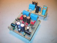
Hi Ivo. Just finished the board, it will be put in the same chassis as the BoZ I am working on. How do you adjust the trimpots; what do you measure where? The smaller board is a regulated "Zen-style" psu for the riaa, it will just tap the BoZ's 60v supply and gives a steady 24v. Hope it will be quiet enough
Here is a pic, just in case you care to see
Steen
The smaller board is a regulated "Zen-style" psu for the riaa, it will just tap the BoZ's 60v supply and gives a steady 24v. Hope it will be quiet enough Here is a pic, just in case you care to see
Steen
Attachments
steenoe said:Hi Ivo. Just finished the board, it will be put in the same chassis as the BoZ I am working on. How do you adjust the trimpots; what do you measure where?
Here is a pic, just in case you care to see
Steen
Beautiful work Steen. You have more projects on the works than anybody I can remember. Are you also working on the KSA50?
Yes, Tony I tend to start up a lot of projects. Everytime I see something exciting; I want to build it Somehow I do manage to finish them all, though Not necesarily at the deadline After I finish the F2 and the BoZ with Riaa, I really have to finish my A-X monoblocks and a X-CCS-BosoZ. The NS10 will be a little job in between. After that I am planning on a pair of Aleph 5, monoblocks (but they might turn into a J-fet version if, someone manage to offer some of those power J-fets for sale!). The KSA50 will have to wait a bit. Its not nearly as appealing as Mr. Pass's creations While all that is going on, I enjoy my BosoZ with the Pearl, and my ZenV4 This is indeed a great hobby
Steen
Somehow I do manage to finish them all, though Not necesarily at the deadline After I finish the F2 and the BoZ with Riaa, I really have to finish my A-X monoblocks and a X-CCS-BosoZ. The NS10 will be a little job in between. After that I am planning on a pair of Aleph 5, monoblocks (but they might turn into a J-fet version if, someone manage to offer some of those power J-fets for sale!). The KSA50 will have to wait a bit. Its not nearly as appealing as Mr. Pass's creations While all that is going on, I enjoy my BosoZ with the Pearl, and my ZenV4 This is indeed a great hobby Steen
Adjustment
Hi !
The small trimmer is used to adjust the operating point. First step is to trim the output voltage to roughly 12V. (measured over the 560 ohm resistor R112/212) After some time fine trim the circuit, so that the voltage over the 12kohm resistor R115/215 is nearly zero. You will see some temperatue drift and the adjustment is somewhat supply voltage dependent.
Thanks a lot, Ivo. I will get right to itAdjustment
Hope to have a listen today. Will keep you posted.Steen
I am having a little trouble, getting this up and running. When connecting the preamp, the speakers sounds excactly like a pulse(heartbeat ) the sound follows the volume, and the music follows the pulse! The woofers looks like a beating heart! What can I have done wrong or what can cause this? I also noticed that the supply voltage drops about 5-6 volts, when connected to the RIAA. I just connected another supply, but that didn't help. The only difference from the schematic is that the trimpot is only 200r instead of 250r.
I also tried with 500r, with the same result. Otherwise everything is as per schematic. Also, I cant get a steady reading across r112/r212 and r115/r215. The digits keeps drifting.
Any suggestions?
Steen.
) the sound follows the volume, and the music follows the pulse! The woofers looks like a beating heart! What can I have done wrong or what can cause this? I also noticed that the supply voltage drops about 5-6 volts, when connected to the RIAA. I just connected another supply, but that didn't help. The only difference from the schematic is that the trimpot is only 200r instead of 250r. I also tried with 500r, with the same result. Otherwise everything is as per schematic. Also, I cant get a steady reading across r112/r212 and r115/r215. The digits keeps drifting.
Any suggestions?
Steen.
- Status
- This old topic is closed. If you want to reopen this topic, contact a moderator using the "Report Post" button.
- Home
- Amplifiers
- Pass Labs
- Phono for Bride of Zen