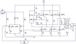
So, I've been simulating the Aleph30 (with a few adjustments) to get somewhat familiar with the current source setup. I want to double the output stage and feedback and use this for an AlephX.
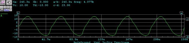
So, I turn up the frequency on the input to 20Khz, and the waveforms start to get a wierd kind of slant to them. Can anyone help me out as to the cause of this, and how I can improve my design? I've attached the circuit and the waveforms. THanks.
Steve
So, I turn up the frequency on the input to 20Khz, and the waveforms start to get a wierd kind of slant to them. Can anyone help me out as to the cause of this, and how I can improve my design? I've attached the circuit and the waveforms. THanks.
Steve
Attachments
Banned
Joined 2002
What about the bias current?
Respect with the original Aleph design, it seems that the resistor that helps to build the "fixed part" of the variable current source ( you can find it between the Q2 base and the R6-R7 node) is missed.
Anyway this resistor is not needed, if you set the quiescent bias current only by the R8 voltage drop, this is not the problem...
Hi William
While the differential input stage would indeed work with just one of these resistors in place, it is definitely never false to have the same load on both branches of a differential amplifier. I do admit that the load seen by the MOSFET - where the signal is taken off from - does not only see the resistor as load but also the input impedance of the mosfets it drives. But I don't think that the presence or absence of the second resistor would cause the anomalities seen above.
But this is just a small detail compared to your suggestion to connect the gates of the output MOSFETs to the other input MOSFET's drain => THIS WOULD DEFINITELY GENERATE A NICE OSCILLATOR!")
SteveG
If the amp's bias is O.K. then the effect might be caused by slew-rate limitation. Being an asymmetrical circuit it might of course have asymmetrical sle-rate capabilities causing the asymmetry seen. If you run your simulation with a rectangular input signal you might probably see different slew rates for the rising and falling edges.
Remember that a given output signal of sinusoidal shape will call for a slwe rate of more than
2*PI*frequency[Hz]*vpeak[V]
The result comes in Volts/second. You have to divide it by one million to get the usual Volts/microsecond.
Regards
Charles
While the differential input stage would indeed work with just one of these resistors in place, it is definitely never false to have the same load on both branches of a differential amplifier. I do admit that the load seen by the MOSFET - where the signal is taken off from - does not only see the resistor as load but also the input impedance of the mosfets it drives. But I don't think that the presence or absence of the second resistor would cause the anomalities seen above.
But this is just a small detail compared to your suggestion to connect the gates of the output MOSFETs to the other input MOSFET's drain => THIS WOULD DEFINITELY GENERATE A NICE OSCILLATOR!
SteveG
If the amp's bias is O.K. then the effect might be caused by slew-rate limitation. Being an asymmetrical circuit it might of course have asymmetrical sle-rate capabilities causing the asymmetry seen. If you run your simulation with a rectangular input signal you might probably see different slew rates for the rising and falling edges.
Remember that a given output signal of sinusoidal shape will call for a slwe rate of more than
2*PI*frequency[Hz]*vpeak[V]
The result comes in Volts/second. You have to divide it by one million to get the usual Volts/microsecond.
Regards
Charles
Thanks for all the help
JasonL,
It is Circuitmaker student edition- freeware, but limited to 50 components. Seems easy to use. I can't remember the address- try searching google.
I will try to exaggerate the effect when I get home tonight(I don't have the circuit on this computer). In it's worst form, it was the waveform plus a smaller double hump on the trailing edges. The only thing I can think of is that there is something asymmetrical as far as impedances go with the input and the feedback arrangement. There is no attempt to make the input impedances equal in this circuit, as it will be completely symmetrical when it is finished (alephX). That may be the whole problem. I hope that this is worked out when I add the other half of the output stage, and use the X feedback arrangement. It would be nice to know that it works before I go and build it, if you know what I mean. I know that it is swinging close to the rails right now. Maybe that is some of the problem. At least with this attempt I have been able to test the Aleph current source and adjust the AC current through the feedback resistors, etc. as in Zen Variations Part 2. That was my goal anyway. I guess I just started to worry when I didn't get a nice looking waveform. Anyway, I would like to know what is causing the problem, in case I end up building an Aleph someday. Also, just for the sake of learning something. I appreciate all the help... please keep the suggestions coming.
steve
Re: Thanks for all the help
Yes that certainly sounds like 2nd harmonics ... does it look like this picture?
Even harmonics are part of the package with Single Ended designs like the Aleph although the harmonics are usually well below 1% unless you are running well into clipping.
SteveG said:In it's worst form, it was the waveform plus a smaller double hump on the trailing edges.
Yes that certainly sounds like 2nd harmonics ... does it look like this picture?
Even harmonics are part of the package with Single Ended designs like the Aleph although the harmonics are usually well below 1% unless you are running well into clipping.
Attachments
Hi SteveG
The waveform is very typical of an amplifier of this type.
Even my own SE Class A amp produces the same waveform at the same frequency.
From my own experiments, it appears to be caused from a lack of open loop gain. To prove this I have added an extra stage to the same amplifier and the problem when away.
Another thing you could try to prove this theory is to remove all but one pair of o/p devices. If it is truely slew induced distortion then by removing o/p devices, you are removing additional gate Capacitance and HF distortion should be reduced.
If however no change is seen then it might be possible that it really is a lack of open loop gain.
I would reduce the 0.47 ohm Source resistors too 0.22 I believe they might be a bit too high. They might provide local feedback but they also reduce open loop gain at HF and beyond.
I hope this might help you, then again I could be barking up the wrong tree.
Regards
Anthony Holton
www.aussieamplifiers.com
SteveG,
How does the the REAL aleph circuit simulate? Butchering the circuit and then starting a thread as to why it doesn't work is to the point of being offensive. Already people are being unsuccessful when attempting the actual circuit, are we actually to have to start dealing with people that deliberately modify it, and then complain?
How does the the REAL aleph circuit simulate? Butchering the circuit and then starting a thread as to why it doesn't work is to the point of being offensive. Already people are being unsuccessful when attempting the actual circuit, are we actually to have to start dealing with people that deliberately modify it, and then complain?
Hi grataku
I don't understand why playing around with a circuit should be offensive.
And I didn't understand SteveG's question as being a complaint but simply as a technical question.
Even though Nelson Pass is definitely a gifted audio engineer I don't think his circuits are so sacrosanct that it woldn't be allowed to play around with them.
In my opinion somobody learns more by building something by himself than by buying a finished product.
But I also think someone learns even more when he is trying to develop/modify something by himself.
regards
Charles
playing around with a circuit
AMEN! What is so different in doing it in simulation than the hundreds of posters that have done it actually building circuits. One has to remember also that commercial designs are done with the constraints of cost, manufacturability, and available parts. I would even bet Mr. Pass might do some things a little different on the designs given his present knowledge, like making the amps an inverting instead of non inverting design. Building a circuit "one off" alows much greater freedom in how an amp is to be designed and built and is one off the main reasons to do it.
H.H.
Guys n Gals (if any),
If you look closely, it appears.. OK to me... that both slopes have that bend. This looks to me like crossover distortion.
I know I know, don't yell at me! I know it is a class A amp. But... it still looks like crossover distortion.
But what do I know?
Gabe
If you look closely, it appears.. OK to me... that both slopes have that bend. This looks to me like crossover distortion.
I know I know, don't yell at me! I know it is a class A amp. But... it still looks like crossover distortion.
But what do I know?
Gabe
Gabevee said:If you look closely, it appears.. OK to me... that both slopes have that bend. This looks to me like crossover distortion.
I know I know, don't yell at me! I know it is a class A amp. But... it still looks like crossover distortion.
I'm sorry, but that is just not possible.
HH,
a rational approach to simulating a working design... do we all agree the aleph is a proven, working design? is to first try the real thing and then modify it. The rest is pure ******** and you are free to argue about why steve is getting a f-ed up output from his "adjusted design" till dawn.
I also "strongly disagree" with you on what Nelson design philosophy may be. It is "high end" cost no object we are talking about here not mass produced GE stereo for sale at sears.
What goes into Pass Labs designs is probably the best of what the company has to offer in terms sonics, reliability and innovation. I hardly think some guy playing around with its freeware simulation software will be able to improve and streamline the design.
"high end" cost no object
The Aleph amps are probably not cost no object designs. Mr. Pass
builds amps to make a living. The Alephs were very good values and an exellent topologies. I do think there is room for improvement as far as parts quality is concerned. Increasing the supply capacitance, Soft recovery diodes, and even regulated power supplies are changes that I think even Mr. Pass would agree are worthwhile areas to experiment with. I have done these type changes to my Aleph 3 with very definite sonic improvments. I also changed the voltage references to LEDs for the current sources for the front end. I am not claiming to know more than Mr. Pass but I am not constrained by the requirements for production amplifiers.
H.H.
P.S. I have built high end products before as well as doing profit improvement and cost reduction design for telecom. My last design was built in quantities of over a million per year and had to be super reliable.
- Status
- This old topic is closed. If you want to reopen this topic, contact a moderator using the "Report Post" button.
- Home
- Amplifiers
- Pass Labs
- Aleph simulation- strange waveforms