...but with a twist: There won´t be any X-feedback!
Well, lets start from the beginning:
Earlier this year I found three huge heatsinks on a junkyard, probably big enough to dissipate some 200W each.
A while later I bought eight cheap 66500uF 35 (or are they 40?) V caps, and yesterday a 750VA 2x24V toroid arrived in my mail.
My original plan was to build a SoZ with constant currents sources in the "tail" to improve the efficiency. I have a pair of 11,5V 160VA transformers that could supply the negative rail voltage.
Still, this would end up with some 500-600W of heat which would change the temperature in my apartment quite drastically.
I want the high output Z of the original SoZ, since I believe my fullrange drivers with BL horns would like that (They sound much better since I ditched the feedback in one of my SE tube amps).
The speakers are also reasonably sensitive, I can play quite loud with less than 1W.
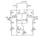
Last night I surfed passdiy.com for inspiration and took a closer look at the ZV7 (the resistor version). It seems to me that it only requires some minor modifications in order to get rid of the X feedback (I must be the first to want this...).
The original circuit works with a single 50V rail and consumes some 300+ watts per channel, which is exactly what I don´t want. If I lower the rail to 32V and the bias to about 2A per Mosfet the power consumption drops to about 130W per channel.
Output power should be in the 5W region, good enough for me.
Some technical issues: R1 and R2 sets the feedback ratio, so I´ll remove them. Instead there will be a 47k resistor between the gate and the junction of R3 and P1 (looking at one half of the circuit, the other will of course be similar) to increase the input impedance.
In order to set the gain we need source resistors, say 0,47 ohms per mosfet.
I´ll see if I can post a schematic later today to clear things up a bit.
Cheers!
Well, lets start from the beginning:
Earlier this year I found three huge heatsinks on a junkyard, probably big enough to dissipate some 200W each.
A while later I bought eight cheap 66500uF 35 (or are they 40?) V caps, and yesterday a 750VA 2x24V toroid arrived in my mail.
My original plan was to build a SoZ with constant currents sources in the "tail" to improve the efficiency. I have a pair of 11,5V 160VA transformers that could supply the negative rail voltage.
Still, this would end up with some 500-600W of heat which would change the temperature in my apartment quite drastically.
I want the high output Z of the original SoZ, since I believe my fullrange drivers with BL horns would like that (They sound much better since I ditched the feedback in one of my SE tube amps).
The speakers are also reasonably sensitive, I can play quite loud with less than 1W.
Last night I surfed passdiy.com for inspiration and took a closer look at the ZV7 (the resistor version). It seems to me that it only requires some minor modifications in order to get rid of the X feedback (I must be the first to want this...).
The original circuit works with a single 50V rail and consumes some 300+ watts per channel, which is exactly what I don´t want. If I lower the rail to 32V and the bias to about 2A per Mosfet the power consumption drops to about 130W per channel.
Output power should be in the 5W region, good enough for me.
Some technical issues: R1 and R2 sets the feedback ratio, so I´ll remove them. Instead there will be a 47k resistor between the gate and the junction of R3 and P1 (looking at one half of the circuit, the other will of course be similar) to increase the input impedance.
In order to set the gain we need source resistors, say 0,47 ohms per mosfet.
I´ll see if I can post a schematic later today to clear things up a bit.
Cheers!

but why omitting the X?
I want the higher output impedance to match with my fullrange horns. I guess it could be changed back to an X if it doesn´t sound good this way.
The amp will run hot as hell
Don´t they all?

- Status
- This old topic is closed. If you want to reopen this topic, contact a moderator using the "Report Post" button.
- Home
- Amplifiers
- Pass Labs
- Zen V7 coming up...