I was adjusting the left channel of the input board on my BA-3 when two of the meter leads made contact (I'm not sure which). The fuse didn't blow, the the amp immediately lost power. I measured ~250mV to ground on the positive supply and ~90mV to ground on the negative side. I pulled one of the filter caps from the positive supply, and it's reading 0uF. Nothing looks burned or charred.
What should I test, and what is most likely blown? Both power supplies? More?
What should I test, and what is most likely blown? Both power supplies? More?
The fuse didn't blow
I had a 3A slow-blow on both hot and neutral, both are still fine.
The amp lost power. No more output. No more light on PSU board.
Happy to send pics, but of what? Nothing looks damaged or different in any way,
Impossible.I pulled one of the filter caps from the positive supply, and it's reading 0uF.
Of the dead amp and the 0uF capacitor.Happy to send pics, but of what?
Pics or it didn´t happen.
Ok, here are the crime scene photos, you sick voyeurs 
In the picture with the two caps and three resistors, the resistors all read OL.
Turns out the reason I was getting 0uF on the power supply caps is because my meter can't read over 400uF. Tested one by feeding it voltage, and it held it just fine.
The resistors between the two banks all read OL, even when completely pulled from the unit. Same result on the negative side. Could this be user error, or does it make sense that they would fail open like that?
The front-end board seems ok, I checked a couple resistors and the output capacitor on the affected side and nothing looked wrong.
As I said before, nothing looks burned or damaged at all.
It's entirely possible I'm imaging this situation to be worse than it is. I do know for sure that the output stopped, the light on the PSU went away, and I measured ~250mV from + to ground.
Attachments
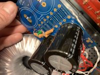
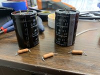
Resistors pictured are 0.47 Ohm.
are or were ?
If it's were , replace them, check for shorts downstream and re-test
are or were ?
If it's were , replace them, check for shorts downstream and re-test
That is their rated value. Currently they read OL.
That is their rated value. Currently they read OL.
Clearly knackered then, they've effectively acted as fuses
Replace them and trace further downstream for possible damage ... your amp should light up again if no shorts.
Oh, it´s not thatOk, here are the crime scene photos, you sick voyeurs
Just think Doctors NEED to see all stark detail to diagnose and work, same here
Ok, now we are talking.Turns out the reason I was getting 0uF on the power supply caps is because my meter can't read over 400uF. Tested one by feeding it voltage, and it held it just fine.
I bet display was just not plain "0" ,if anything it would have displayed cable or hand capacitance, but must also have shown some "OL" or "beyond range" indicator.
Ok, let´s go on:
Not common in plain film/composition resistors unless they explode r burn to a crisp, but normal failure in wirewound ones like those.The resistors between the two banks all read OL, even when completely pulled from the unit. Same result on the negative side. Could this be user error, or does it make sense that they would fail open like that?
Metal wire simply melts away.
Closeup pictures and/or labelling would have cleared this detail earlier on.
As you see, the "gore" pictures are actually useful.
Cool, but you are just testing at random, no method to it., I checked a couple resistors and the output capacitor on the affected side and nothing looked wrong.
That is the loooooooooooooonnnnnnnggggg path.
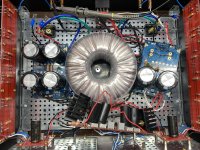
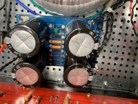
One detail show in actual pictures but not on verbal communication:you have small TO220 or similar case supporting 6X larger heatsinks, floating unsupported.
That weight and any case movement, even putting upside down for inspection, will flex and crack those tiny legs.
Today we focus on repairing your amp, but tomorrow and not later, we correct that "mechanical" problem.
I see it´s a DIY Audio amp, perfect.
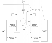
Care to post here at least the wiring/block diagram
because we´ll have to separate parts to check block by block.
Build a lamp bulb current limiter, remember we need a tiny red hot tungsten wire inside the limiting bulb, not LED/CFL/etc. "equivalent".
Suggest 40 to 75 *real* Watts, you can still buy this kind of bulbs:
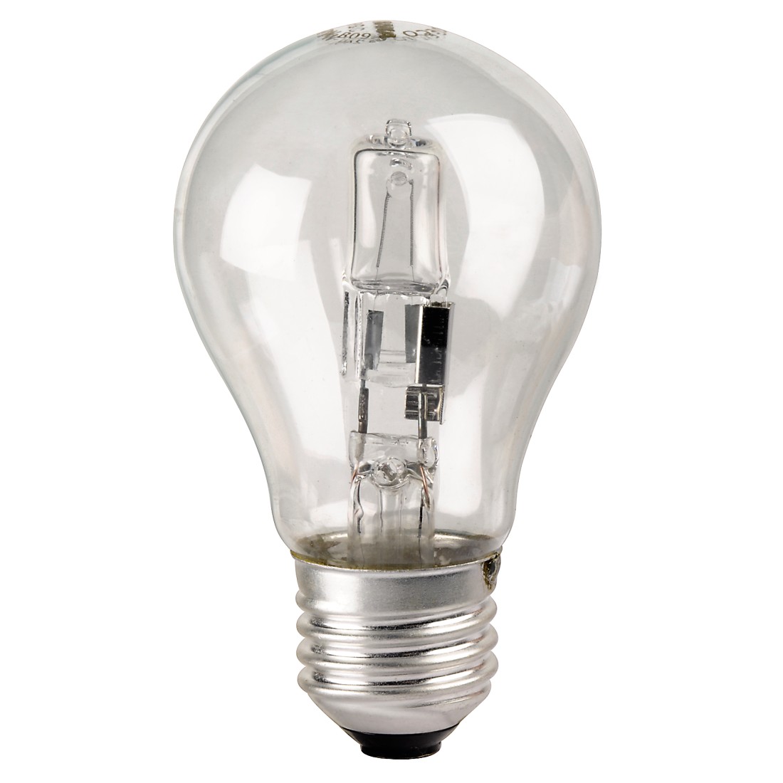
IF fuses blow again (an distinct possibility), this limiter will let amp turn on anyway and measure something, call it an intelligent fuse if you wish.
Maybe, but also measure voltage before and after them.Fuses are fine, as I said before.
Ok,they are blown open.That is their rated value. Currently they read OL.
I suspect blown/shorted power semiconductors, but let´s follow Jan Didden´s suggestions on post #12 to a T
In a nutshell and following the minimum damage path:
Post block diagram for better communication.
Build lamp limiter.
Disconnect and tape all transformer secondaries.
Turn "amp" (actually transformer only) ON.
Lamp should blink and turn OFF or show red/dark orange filament.
Bright yellow or white means trouble.
If fine, turn amp off, unplug it for safety, then connect ONE power supply (I see two) with disconnected outputs,only ground connected and repeat test.
Lamp should blink brighter but then return to darkish.
Measure expected voltages out of supply.
Notice this test beats pulling all parts to be measured outside one by one by a Light year. At least
If fine,wait for caps to discharge and repeat test with other supply, same conditions.
Enough homework for today.
I hope this diagram is useful.
Thanks for the long post! I appreciate it.
Yes, was OL, I am dumb.
Those resistors are metal film, 3W. Are the following part:
https://www.mouser.com/ProductDetail/Vishay-Dale/CPF3R47000JNB14
Yes. Did have that problem. Reenforced legs on three with solder. Broke and repaired legs on fourth with wire.
There was no recommended part specified in the build guide, so I wasn't sure what to order, or what would fit physically on the board. So, that's what I got. If you can suggest a part that would be superior, I would happily order it.
Have variac. I assume this will suffice. If not, please specify.
I assume this would be the rectifier diodes?
I am getting correct 24vac out of the secondaries. I have not measured past the diodes yet.
I will continue testing progressively as you suggest. I assume I can run the power supplies without the PI resistors in place, just using jumpers, as the PI resistors just provide filtering, which isn't *strictly* necessary, yeah? The LED, bleeder resistors, and snubber resistors/cap all test fine.
Thanks for the long post! I appreciate it.
I bet display was just not plain "0"
Yes, was OL, I am dumb.
Not common in plain film/composition resistors unless they explode r burn to a crisp, but normal failure in wirewound ones like those.
Those resistors are metal film, 3W. Are the following part:
https://www.mouser.com/ProductDetail/Vishay-Dale/CPF3R47000JNB14
One detail show in actual pictures but not on verbal communication:you have small TO220 or similar case supporting 6X larger heatsinks, floating unsupported.
That weight and any case movement, even putting upside down for inspection, will flex and crack those tiny legs.
Yes. Did have that problem. Reenforced legs on three with solder. Broke and repaired legs on fourth with wire.
There was no recommended part specified in the build guide, so I wasn't sure what to order, or what would fit physically on the board. So, that's what I got. If you can suggest a part that would be superior, I would happily order it.
Build a lamp bulb current limiter
Have variac. I assume this will suffice. If not, please specify.
I suspect blown/shorted power semiconductors
I assume this would be the rectifier diodes?
Disconnect and tape all transformer secondaries.
Turn "amp" (actually transformer only) ON.
Lamp should blink and turn OFF or show red/dark orange filament.
I am getting correct 24vac out of the secondaries. I have not measured past the diodes yet.
Enough homework for today.
I will continue testing progressively as you suggest. I assume I can run the power supplies without the PI resistors in place, just using jumpers, as the PI resistors just provide filtering, which isn't *strictly* necessary, yeah? The LED, bleeder resistors, and snubber resistors/cap all test fine.
Attachments
I'd wait for the clearly failed resistors to turn up and then:
If you have the variac you should be able to run it up to 20VAC fairly safely without killing anything further and you'll hear from the variac if there's a remaining problem as you start to wind it up to 20v.
If the variac doesn't grumble at 20VAC take some measurements at various points (they'll obviously all be way under normal voltages) but you will be able to safely prod about making various voltage checks, on PSU and both channels base voltages , and bias points etc
If both PSU's are coming up ok, you can put some more variac on, say 40VAC, then check some more..
When I say safely I mean at low enough DC voltages to not blow components. but bear in mind your variac is not isolated.
Last edited:
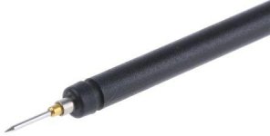
Whilst on the subject of the cause of your woes, get yourself some of Hirschmann 972318101 probes , there is a black one too..
The super super sharp ** spikes are spring loaded , so you will not slip off solder or tracks...
(They are truly **** off sharp believe me)
You will not regret getting one at least, leave the standard blunt probes you get with meters for electricians
Their only downside is the tip snaps if you stand on the probe
Attachments
Ok, update: Both PSUs work correctly up to 120vac input (both produce +/- 34vdc as expected). I've got them running with a single jumper where the PI resistors would go.
Those probes look nice.... The issue I had was that I had a web of clips hooked up, measuring the bias across both transistors and the DC offset for the left channel front end. It was late, I was getting sloppy, and I pushed on the board making adjustments and two of the clips made contact and fused together.
Those probes look nice.... The issue I had was that I had a web of clips hooked up, measuring the bias across both transistors and the DC offset for the left channel front end. It was late, I was getting sloppy, and I pushed on the board making adjustments and two of the clips made contact and fused together.
- Home
- Amplifiers
- Pass Labs
- Shorted meter leads, now no power, where start fixing?