agreed ZM. Scope probe earth wire - if used on non mains earth referenced load, will result in load going to house mains earth, as scope is mains earth referenced.
Should 4 turns either direction from P3 centre position, be enough to alter the harmonic levels (in my case it never did), or should I try maybe 4~6 turns from centre? I dont want to cook things
My P3 pots are 30 turns stop to stop
Do the harmonics respond instantaneously to P3 movements or I should wait a bit for things to respond?
edit: just read about sound cards producing their own distortion that can overtake FFT results of an amp.
Is there not a way of scope mathematically deducting a sound cards distortion from the amp result? ie. CH1 (amp) - CH2 (sound card out)??
Last edited:
can't remember - was long time ago when I did play with P3 on F5, so number of turns ....
better to someone more fresh chime in with answer
though - when doing P3 exercise - it's good to have both DVMs, needed for DC Offset and Iq setup, connected ; so you can each time making a step with P3 pause signal, re-check both Iq and DC Offset and correct those with P1 or P2, then proceed THD Spectra check with signal
process is iterative, involving operation of all 3 trimpots
ok ZM will do, good info - thanks.
I just ran the FFT on the sound card.. its riddled with 2H, 3H ect. BUT if I keep its output below 900mV its clean. So I'll retest the F5 again later today and keep close tabs on the cards harmonics this time.
Also scope maths just may work, no doubt it will deduct all the cards output, but the result should be just what the F5 is adding - will test this and see what gives
scope is really here, besides sound card as main tool, "just" to show you output sine
you can easily use proper DVM set to Vac, and it'll show you directly Vrms
when I'm doing THD measurements, I'm having both DVM and scope connected on output of amp - my brain is thinking in Vpp so I need to have Vrms shown ....... while scope is feeding graphic nature of my brain ...... and finally showing (first signs of) clipping
one thing - my scope is safety-GND-free, from eons ago ...... fed from isolation xformer (floating) so I don't need to care about mess-up with wrongly connected neg of scope probe
eons ago, after dozen fuses blown while I was repairing one PA amp (ton heavy), I finally realized that I connected black probe to live output ....... so drastic stupidity demanded drastic measures
I built an ACA and was quite blown away, then did an F5.
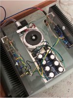
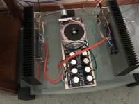
The F5 isn't housed in a chassis yet, but wires are fairly well separated.
Its got maybe 15hrs on it. It seems to be missing something in the upper bass, the acoustic bass in Tears in Heaven by Clapton (live) has almost disappeared, its very faint.
The ACA presents the same song bewdifully!
Checked all phasing which was fine, yet the lower bass registers are also fine. I noticed the upper bass missing in quite a few other CD's but never really nailed exactly what was missing until I played Tears in Heaven.
F5 bias is set at 0.59vDC, DC offset 10~15mV.
I have P1 mounted, set mid range (30 turn pots) so set at 15 turns
Heatsinks are static at 39degC
Rails are +/- 22.8vDC
It's using the following;
Antek 5218
Monolithic 35A Rectifiers
16 gauge wire for DC power
Twisted CAT5 for inputs
16 gauge output wire
120,000uF Caps total (+ and -)
When I changed the ACA v1.8 out for the F5, I changed nothing else.. just the amps.
Your wiring is too long and all over the place. Usually, when a piece of a spectrum does not sound right, the issue is related to an incorrect power supply impedance. FW amplifiers do not have any local power DC rails' decoupling on AMP PCB's..., so you could search on this topic as well (the local decoupling would require a complete re-think with regard to AMP PCB design...)
I'd look at how to properly wire the amp, how to properly route grounds and common returns. Nelson has posted in one of the threads, a picture of a screw with proper placement of the common (negative) returns. This can be implemented with that PS PCB (only just...) - not all ground points on that PCB are interchangeable, the ones closest to the caps should be used for the connection to the chassis (and here... only a DC thinking has been used on so many builds, with very long and thin NTC wires in the return path... you have to start thinking AC / RF-noise here...), then comes the speaker common return; the one further away from the capacitors should be used for small signal returns. This will make a huge difference in sound.
For example... An audio amplifier needs a very low output impedance to drive a loudspeaker; yet, so many builds (yours included) have speaker common return going to AMP PCB first, and then back to PS PCB (usually via the same cable that carries the small-signal return !!). This should get you started I hope.
EDIT: I had a close look at your PS PCB - the only capacitors doing filtering are the large electrolytes. That can't be good, especially with nil AMP PCB's local decoupling.
Last edited:
S-Lost... your correct, sorry typo, P3 is set at mid point (15 turns).
I'm using a Krell Showcase Pre, I dont believe it reverses phase. I haven't had this problem with other amps I've used in this system.. like Rotel, Krell, Parasound, Luxman & the ACA.
I tried reversing the rectifier inputs, that made no difference.
Have double checked all other phasing on this F5, it all looks good.
Will try taking the bias up while watching temps. I understand I can increase bias to just below the point of current draw taking off. Does anyone know roughly what bias voltage this usually starts to occur on an F5?
Unfortunately I cant find my DMM Clamp so dont have a means to monitor current draw at the moment
Reversed phase or no, you shouldn't be having a bass deficiency with that amp.
Russellc
the bass deficiency issue is already resolved, explained earlier in the thread.
Extreme Boky, you have raised some great points that I will look into next. Please be patient with me and hang around, its just I'm a bit busy with work at the moment.
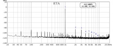
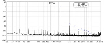
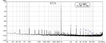
I ran the F5 on FFT. CH1 on input, CH2 on output (4 ohm load). DMM's watching bias and DC offset
Its not possible on my scope to math deduct CH1 from CH2 and FFT the result, so simply ensured 1KHz sine wave in was clean of harmonics before looking at CH2.
The amp harmonics responded to P3 movements, I knocked the H3 down a tad then re-biased. Just need time now to sit down and sound test results... will do later this week.
Extreme Boky, you have raised some great points that I will look into next. Please be patient with me and hang around, its just I'm a bit busy with work at the moment.
I ran the F5 on FFT. CH1 on input, CH2 on output (4 ohm load). DMM's watching bias and DC offset
Its not possible on my scope to math deduct CH1 from CH2 and FFT the result, so simply ensured 1KHz sine wave in was clean of harmonics before looking at CH2.
The amp harmonics responded to P3 movements, I knocked the H3 down a tad then re-biased. Just need time now to sit down and sound test results... will do later this week.
Last edited:
OK I'm going to attack this hum I've got. Before I do can someone confirm please I can safely do any of the following in tracking down the hum:
can speaker "-" be wired directly to chassis?
can input "-" be wired directly to chassis?
can amp PCB ground be wired directly to chassis?
can PSU PCB ground be wired directly to chassis (with no thermister)?
can speaker "-" be wired directly to chassis?
can input "-" be wired directly to chassis?
can amp PCB ground be wired directly to chassis?
can PSU PCB ground be wired directly to chassis (with no thermister)?
I have 2 grounds as follows;
1 - mains earth in direct to chassis
2 - psu PCB earth to chassis via thermistor, CL-60
both of the above are seperate earth points on the chassis
I just swapped around the speaker return and PSU ground on the amp PCBs ground points.
So now the speaker return is closest to the line inputs, this has made a dramatic improvement in the reduction of hum, however there is still a very very slight hum there.
Allan, You asked in post #31 about wiring arrangement. The diyAudio F5 build guide shows wiring of the power supply, signal inputs, and speaker outputs.
Firstwatt F5 amplifier v3 - diyAudio Guides
The guide also shows arrangement and location of power supply and power transformer. The location of power transformer can have major affect on hum. Power transformers emit unwanted electromagnetic interference (EMI) that can be picked up by signal wires and audio circuits. The best location for the power transformer is as far away as possible from audio signal circuits and wires, especially low level signal wires.
You have located the power transformer very close to the signal inputs and wires. That is not the preferred location. The build guide shows the best location, at the front of the amplifier, as far away from the input signal wiring as possible. If you look at pictures of factory assembled First Watt amplifiers, the power transformer is located at the front and the power supply board is towards the back.
As mentioned earlier, rotating the transformer to find the best orientation of the transformer should also be done. Antek transformers definitely have noisy and less noisy transformer orientations.
Ben, this sub chassis was really only intended to used for easy testing, tweaking prior to making the final chassis.
I understand the transfo must be furtherest away from low level signals and will take this into account in the final build.
May even flip the transfo on its side too.
I rewired the psu DC out when I swapped speaker return and PSU grounds on amp PCBs.
Since, after about 30mins of running things seemed to have quietened down even more.
The hum now is almost not even a concern.. I'm struggling to hear it, so I'm calling the hum issue resolved and will move onto the chassis build.
I feel very confident in the final build with transfo repositioned she'll be dead silent.
E-Boky.. will do a hum test with inputs shorted later today and advise outcome.
I didnt pay enough attention to the wiring in the build guides, was to eager to get it up and running.
Hope this is a lesson for others!
Thanks everyone for the great pointers, I've learnt a lot
Attachments
Last edited:
Time to revisit comments made by EB here..Your wiring is too long and all over the place. Usually, when a piece of a spectrum does not sound right, the issue is related to an incorrect power supply impedance. FW amplifiers do not have any local power DC rails' decoupling on AMP PCB's..., so you could search on this topic as well (the local decoupling would require a complete re-think with regard to AMP PCB design...)
I'd look at how to properly wire the amp, how to properly route grounds and common returns. Nelson has posted in one of the threads, a picture of a screw with proper placement of the common (negative) returns. This can be implemented with that PS PCB (only just...) - not all ground points on that PCB are interchangeable, the ones closest to the caps should be used for the connection to the chassis (and here... only a DC thinking has been used on so many builds, with very long and thin NTC wires in the return path... you have to start thinking AC / RF-noise here...), then comes the speaker common return; the one further away from the capacitors should be used for small signal returns. This will make a huge difference in sound.
For example... An audio amplifier needs a very low output impedance to drive a loudspeaker; yet, so many builds (yours included) have speaker common return going to AMP PCB first, and then back to PS PCB (usually via the same cable that carries the small-signal return !!). This should get you started I hope.
EDIT: I had a close look at your PS PCB - the only capacitors doing filtering are the large electrolytes. That can't be good, especially with nil AMP PCB's local decoupling.
With the speaker return, should I route the speaker return to the PSU PCB ground first, then jump from it over to the AMP PCB?
I tried searching for the post by Nelson EB refers too.. "A Screw with proper placement of common (negative) returns" - I cant find this post ?!?
Has anyone created a wiring schematic that outlines all this?
Thanks AL
6moon is great place - to see big pics of FW amps with lid off
when I was young (which still I am) they taught me that best knowledge is stolen one ..... meaning - what you get with own deduction is more worthy than served on plate
I mean - Papa's practice is to bring GND wire to channel pcb, then route it from there to output post
but - what I said - you can learn plenty of tricks just starring at proper pics of quality build
lately, I'm mostly starring at Goats; uberfunny, thus uberbenefits
- Home
- Amplifiers
- Pass Labs
- F5 & acoustic bass, where is it?