You're right, it is too complicated for me. My brain can't comprehend it.......
it's simple
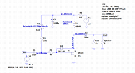
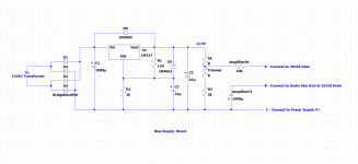
left is input JFet buffer, loaded with simple ring-of-two CCS (to neg-neg leg), cascoded with proper flying/constant-voltage cascode
0R11 in rail above is where we are monitoring Iq, with optodiode
voltage sag across 0R11 is not enough for optodiode, so we are adding some voltage with additional current through 270R ; that role - my fave precision CCS - LT3092
optobjt connected from input JFet gate (100K shunt/bias conductor) to neg-neg leg, while 47K from top rail is current conductor there, acting as adjustable pushrod ......... when current through 0R11 is rising, 47K pushrod is pushing JFet gate down
and opposite .......... when current through 0R11 is decreasing, 47K pushrod is pulling JFet gate up ......... so it is more conrod

easy peasy
Thanks for the explanation. The wheels in my head are now spinning up and the light bulb is glowing dimly. I am slowly finding my way.
I am going to input some of the sub-circuits into LTSpice to get a better understanding. LTSpice is a great tool for helping me understand how circuits work.
I am going to input some of the sub-circuits into LTSpice to get a better understanding. LTSpice is a great tool for helping me understand how circuits work.
The right channel is finished. I had built and tested in stages, and the completed channel was powered up for the first time this evening. With a dim bulb tester (DBT) in place and with the bias voltage set at maximum, there was no current draw and Vds was correct. Lowering the bias voltage started the current flowing, so no issues. With the DBT removed, the channel was powered up and Iq was adjusted successfully. At Iq=1.5A, V+=22.7V, Vgs=5.8V, and Vds=-22.0V, more or less as expected.
Some performance tests tomorrow but meanwhile here are the schematics and pictures:
Some performance tests tomorrow but meanwhile here are the schematics and pictures:
Attachments
-
 SE 2SJ28 Choke Loaded Common Drain Amplifier Schematic - V+ 22V.png52 KB · Views: 478
 -
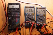 Right Channel Vgs, Vds, Iq divided by 10.jpg677.5 KB · Views: 264
 -
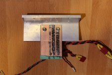 2SJ28 choke loaded follower VFET connection board-bottom.jpg722.1 KB · Views: 226
 -
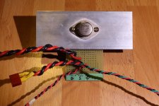 2SJ28 choke loaded follower VFET connection board-top.jpg704.9 KB · Views: 219
 -
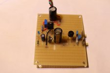 2SJ28 choke loaded follower bias supply.jpg370.1 KB · Views: 215
 -
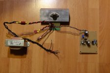 2SJ28 choke loaded follower right channel wiring.jpg727.4 KB · Views: 241
 -
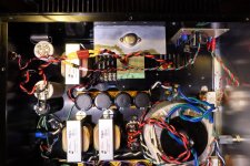 2SJ28 Choke Loaded Follower Right Channel - top view.jpg720.4 KB · Views: 373
 -
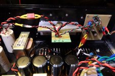 2SJ28 choke loaded follower right channel.jpg662.9 KB · Views: 405
 -
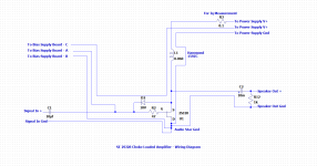 SE 2SJ28 Choke Loaded Common Drain Amplifier Wiring Diagram .png41 KB · Views: 429
 -
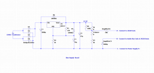
 Bias Voltage Supply.png40 KB · Views: 468
Thanks for the great comments. 
ZM, No bias voltage would be disastrous for the VFET if the wiper fails. I do see other SIT/VFET circuits with no anti-Gremlin part. I have not had a trimmer fail but I suppose it can happen, although in this circuit only a couple of mV is going through it and dissipation is about 0.02W.
ZM, No bias voltage would be disastrous for the VFET if the wiper fails. I do see other SIT/VFET circuits with no anti-Gremlin part. I have not had a trimmer fail but I suppose it can happen, although in this circuit only a couple of mV is going through it and dissipation is about 0.02W.
Attachments
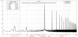
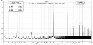
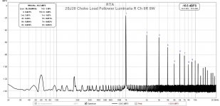
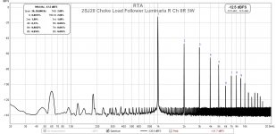
Here are the distortion measurements that I made today. For voltage gain I initially used my ACP+ to get an idea of the follower distortion with minimum distortion from the voltage gain stage. The ACP+ has low gain and combined with the VFET's low transconductance, 1W output was not possible, so I measured the 0.5W distortion from the 2SJ28 follower/ACP+ combination.
Then I used my Luminaria preamp for the rest of the measurements. Included is a 0.5W output for comparison. The Luminaria, with its resistor loaded single ended 2SK82 gain stage, has higher distortion than the ACP+ and also higher distortion than the choke loaded 2SJ28 follower amplifier, so much of the measured distortion is due to the Luminaria.
The maximum output at 8 Ohm output was about 12.5W. I eye-balled the output waveform for onset of clipping.
Attachments
-
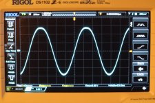 Right Channel 8R Onset Clipping.JPG641.6 KB · Views: 133
 -
 2SJ28 choke load follower Luminaria right ch 8R 12.5W.jpg149.3 KB · Views: 128
 -
 2SJ28 choke load follower Luminaria right ch 8R 10W.jpg147.3 KB · Views: 116
 -
 2SJ28 choke load follower Luminaria right ch 8R 8W.jpg148.5 KB · Views: 348
 -
 2SJ28 choke load follower Luminaria right ch 8R 5W.jpg147.7 KB · Views: 353
 -
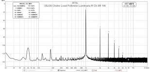 2SJ28 choke load follower Luminaria right ch 8R 1W.jpg147.9 KB · Views: 354
 -
 2SJ28 choke load follower Luminaria right ch 8R 0.5W.jpg148 KB · Views: 378
 -
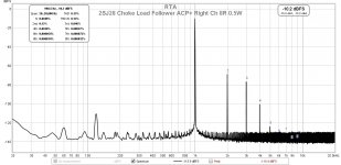 2SJ28 choke load follower ACP+ right ch 8R 0.5W.jpg145.6 KB · Views: 365
I listened to the right channel for a few hours and I was quite happy with the sound. I had one channel of my 2SK180 193V choked loaded follower amp in the left channel along with the 2SJ28 amp in the right channel, and I didn't think that it sounded any different from my other SIT follower amps. I had been listening to my 2SK180 followers for a few weeks before I switched to my THF-51S common drain mu followers for the past two weeks or so, and it seemed to me that they all sound about the same to me. I don't think I would be able to differentiate between them based on sound. They all sound great to my ears. My speakers are 102dB sensitive so the I haven't noticed a lack of power. However I will be able to evaluate that when I get the left channel finished.
For this build I used the Hammond 159ZC as the load choke whereas the Hammond 193V was used in my 2SK180 follower. The 193V was a holdover from my 2SJ28 choke loaded L'Amp (common source) and that was the choke that Michael Rothacher recommended. I also remember the weight of that amp. So for this build I wanted the amp to be lighter. I chose the 159ZC and as I mentioned in post #6, I did some LTSpice simulations and the results looked acceptable.
Now that one channel is built I measured the frequency response and indeed the Hammond 159ZC performed well. According to my measurements the output at 20Hz was down about 0.4dB, and was reasonable flat at 100kHz.
The frequency response was measured manually with a two channel oscilloscope, with an old HP3310A function generator sending a sine wave to the amplifier input. The oscilloscope measured the input and output frequency and voltage level at the amplifier. The input voltage was manually adjusted as required to maintain a set level and the output voltage was recorded. Fine tuning of the function generator's output level was not very precise. It was within 0.01V, so the amplifier output level would therefore have some imprecision too, in the order of approximately 0.01V. So the frequency response measurement is only approximate, but it seems to show not much loss at 20Hz.
Frequency (Hz) Input (Vrms) Output (Vrms) Output (dBV)
20---------------4.03---------------2.93------------9.34
25---------------4.03---------------2.97------------9.46
30---------------4.02---------------2.97------------9.46
35---------------4.03---------------3.01------------9.57
40---------------4.02---------------3.05------------9.69
100--------------4.02---------------3.05------------9.69
250--------------4.03-------------- 3.07------------9.74
500--------------4.03---------------3.08-------------9.77
1k---------------4.03---------------3.07-------------9.74
5k---------------4.03---------------3.07-------------9.74
10k--------------4.03---------------3.07-------------9.74
20k--------------4.02---------------3.05-------------9.69
40k--------------4.02---------------3.05-------------9.69
100k-------------4.02---------------3.04------------ 9.66
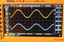
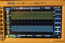
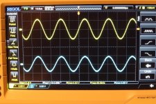
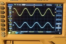
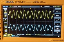
I have attached several images of the oscilloscope measurements, not exciting, but for documentation. It does show a non-inverting output as it should be. The slight droop at the extreme bottom end is probably not noticeable in real life. It definitely is good enough for me. So the Hammond 159ZJ is good enough, costs much less and weighs much less than the 193V. A winner for this amp.
For this build I used the Hammond 159ZC as the load choke whereas the Hammond 193V was used in my 2SK180 follower. The 193V was a holdover from my 2SJ28 choke loaded L'Amp (common source) and that was the choke that Michael Rothacher recommended. I also remember the weight of that amp. So for this build I wanted the amp to be lighter. I chose the 159ZC and as I mentioned in post #6, I did some LTSpice simulations and the results looked acceptable.
Now that one channel is built I measured the frequency response and indeed the Hammond 159ZC performed well. According to my measurements the output at 20Hz was down about 0.4dB, and was reasonable flat at 100kHz.
The frequency response was measured manually with a two channel oscilloscope, with an old HP3310A function generator sending a sine wave to the amplifier input. The oscilloscope measured the input and output frequency and voltage level at the amplifier. The input voltage was manually adjusted as required to maintain a set level and the output voltage was recorded. Fine tuning of the function generator's output level was not very precise. It was within 0.01V, so the amplifier output level would therefore have some imprecision too, in the order of approximately 0.01V. So the frequency response measurement is only approximate, but it seems to show not much loss at 20Hz.
Frequency (Hz) Input (Vrms) Output (Vrms) Output (dBV)
20---------------4.03---------------2.93------------9.34
25---------------4.03---------------2.97------------9.46
30---------------4.02---------------2.97------------9.46
35---------------4.03---------------3.01------------9.57
40---------------4.02---------------3.05------------9.69
100--------------4.02---------------3.05------------9.69
250--------------4.03-------------- 3.07------------9.74
500--------------4.03---------------3.08-------------9.77
1k---------------4.03---------------3.07-------------9.74
5k---------------4.03---------------3.07-------------9.74
10k--------------4.03---------------3.07-------------9.74
20k--------------4.02---------------3.05-------------9.69
40k--------------4.02---------------3.05-------------9.69
100k-------------4.02---------------3.04------------ 9.66
I have attached several images of the oscilloscope measurements, not exciting, but for documentation. It does show a non-inverting output as it should be. The slight droop at the extreme bottom end is probably not noticeable in real life. It definitely is good enough for me. So the Hammond 159ZJ is good enough, costs much less and weighs much less than the 193V. A winner for this amp.
Attachments

The inductance of those chokes typically depends on frequency. I would not be surprised if the 60 mH of the 159ZC relates to 50 Hz or some higher frequency, and the value might well be higher at lower frequencies.
Ben, can you measure the inductance of the 159ZC at different frequencies (just make a voltage divider with the choke and a resistor, and measure the voltage ratio across the divider at different frequencies)?
Ben, can you measure the inductance of the 159ZC at different frequencies (just make a voltage divider with the choke and a resistor, and measure the voltage ratio across the divider at different frequencies)?
nicoch58 and plasnu, The choice of choke was an intentional compromise.
mbrennwa, I will check the inductance at various frequencies.
ra7, I had been using an external 1kHz oscillator instead of the REW signal generator, so I continued with the function generator for frquency response. I will give REW's frequency response mode a try.
I always have time to try something new and exercise my brain.")
mbrennwa, I will check the inductance at various frequencies.
ra7, I had been using an external 1kHz oscillator instead of the REW signal generator, so I continued with the function generator for frquency response. I will give REW's frequency response mode a try.
I always have time to try something new and exercise my brain.
- Home
- Amplifiers
- Pass Labs
- Sony VFET 2SJ28 Single Ended Choke Loaded Follower Amplifier