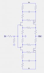
In post #32, the resistors on the drains of the output FETs were intentionally introduced to provide negative feedback of the bias current instead of using optocouplers. I haven't worked out the resistor ratios needed to achieve thermal stability,
Of course, the two circuits (posts #32 and #39) can be combined:
Of course, the two circuits (posts #32 and #39) can be combined:
Attachments

Damn youse! I have that book laid out to start reading next and had no idea it was about time travel. So that's ruined!

Speaking of Time Travel... I'm re-reading William Gibson's "The Peripheral" - a fascinating
twist on Time Travel. Highly Recommended.
The intrigue is building?
Restless Spirit of Greedy Boyz
if not for that, I would start thinking it's orchestrated ....... but no - all merits of
Pavlovian conditioning are evident, from time right after first Zen amp ......
(leave them for a month without new amp, saliva flow is starting)

Restless Spirit of Greedy Boyz
if not for that, I would start thinking it's orchestrated ....... but no - all merits of
Pavlovian conditioning are evident, from time right after first Zen amp ......
(leave them for a month without new amp, saliva flow is starting)
Life is good being Greedy!

Gifts from Pa are treasure!

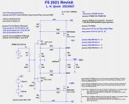
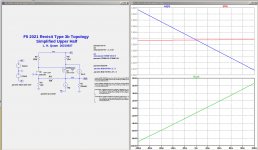
Here is a circuit based on the topology of post #32.
The first image shows a set of very good component values.
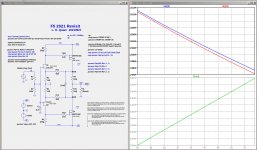
The second image show a temperature sweep from 25C to 60C of the output FETs, and the FET idle currents and the output voltage offset.
Attached is a standalone LTSpice .asc file for the circuit with parameterized values.
The inclusion of a 20Farad supercapacitor between the output FET drains makes a huge difference in the distortion levels. I do not know if the supercapacitor frequency response over the audio range is good enough or not. I am sure this will be controversial.
The first image shows a set of very good component values.
The second image show a temperature sweep from 25C to 60C of the output FETs, and the FET idle currents and the output voltage offset.
Attached is a standalone LTSpice .asc file for the circuit with parameterized values.
The inclusion of a 20Farad supercapacitor between the output FET drains makes a huge difference in the distortion levels. I do not know if the supercapacitor frequency response over the audio range is good enough or not. I am sure this will be controversial.
Attachments
I have checked differently that the bias control works.
I just added a 0.1A current in parallel with Q3, and checked the current through R9,10.
They remain largely unchanged.
So the bias is self regulating, even with such abrupt change in bias.
I am pretty sure it also works in practice.
Patrick
I just added a 0.1A current in parallel with Q3, and checked the current through R9,10.
They remain largely unchanged.
So the bias is self regulating, even with such abrupt change in bias.
I am pretty sure it also works in practice.
Patrick
Amazing!
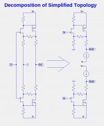
I need to do serious math modeling of the circuit. The F5 topology has a special property that makes it possible to model the two halves independently, since the only connections are the input, output, and ground. This cuts the math equations roughly in half.
I need to do serious math modeling of the circuit. The F5 topology has a special property that makes it possible to model the two halves independently, since the only connections are the input, output, and ground. This cuts the math equations roughly in half.
Attachments
But the output to load is still joint.
It is a transconductance amp in open loop.
So the output is load dependent, and output voltage is sum of two currents x Load impedance.
Distortion on one half will affect the other half.
So you cannot just divide the load into two parallel halves.
And the even harmonics NFB by R9,10 only works when you recombine them into one.
Cheers,
Patrick
- Home
- Amplifiers
- Pass Labs
- Update on Pa's new F5?