Disclaim: DIY at your own risk. No responsibility will be taken if precious amplifiers/speakers are blown.
Introduction
More and more SMPS are used in audio amplifiers. Meanwell desk SMPS for the newest V-FET amplifier is used. The feedback to use SMPS in the amp from all lucky winners is generally positive.
SMPS
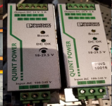
Phoenix Contact Quint-PS/1AC/24DC/5 is selected for the test because of seeing and using them a lot. Its output voltage is 18-29.5VDC adjustable, very handy for future testing and different amps. The output current is 5A, but it has a boost mode, which allows 7.5A at 24VDC if the ambient temperature is not over 40°C. The residual noise is 40mV P-P, which is very low. They can work in parallel to increase the current or series to double the voltage. It is very well built, metal case, 105°C Rubycon and Nichicon capacitors. And all other components look very solid.
The most important feature is the build in protection function. They have built-in protections.
Capacitance Load Test
“True audiophile nervosa” cannot tolerate the oblivion of their best sounding, huge, beautiful capacitors from their beloved amplifier power supply. Some capacitors are be added in.
In the spec, the SMPS used does not list a max direct load capacitance load. But other similar SMPS can have 3000uF-8000uF direct capacitance load. Started from 1000uF and ended with a 10000uF capacitor, the SMPS can start. But one of the PS started oscillation on pure capacitor load. A 4.7K resistor is added and give the PS some small current load to solve the problem.
Introduction
More and more SMPS are used in audio amplifiers. Meanwell desk SMPS for the newest V-FET amplifier is used. The feedback to use SMPS in the amp from all lucky winners is generally positive.
SMPS
Phoenix Contact Quint-PS/1AC/24DC/5 is selected for the test because of seeing and using them a lot. Its output voltage is 18-29.5VDC adjustable, very handy for future testing and different amps. The output current is 5A, but it has a boost mode, which allows 7.5A at 24VDC if the ambient temperature is not over 40°C. The residual noise is 40mV P-P, which is very low. They can work in parallel to increase the current or series to double the voltage. It is very well built, metal case, 105°C Rubycon and Nichicon capacitors. And all other components look very solid.
The most important feature is the build in protection function. They have built-in protections.
Capacitance Load Test
“True audiophile nervosa” cannot tolerate the oblivion of their best sounding, huge, beautiful capacitors from their beloved amplifier power supply. Some capacitors are be added in.
In the spec, the SMPS used does not list a max direct load capacitance load. But other similar SMPS can have 3000uF-8000uF direct capacitance load. Started from 1000uF and ended with a 10000uF capacitor, the SMPS can start. But one of the PS started oscillation on pure capacitor load. A 4.7K resistor is added and give the PS some small current load to solve the problem.
Attachments
Two in Serie, Turn On Test
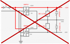
Hooked up two SMPS as shown in figure. Turn on SW, two SMPS not on at same time. Putting this circuit on F4 without speakers, and a turn-on voltage 8.5VDC on the speaker terminals is detected for a half second. The two SMPS cannot be just simply put in series to get +/- power supply.
Hooked up two SMPS as shown in figure. Turn on SW, two SMPS not on at same time. Putting this circuit on F4 without speakers, and a turn-on voltage 8.5VDC on the speaker terminals is detected for a half second. The two SMPS cannot be just simply put in series to get +/- power supply.
Attachments
No Returning
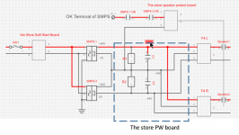
Money paid and the SMPS received. No returning. After the initial tests plus the working experience with the SMPS, the final wiring schematics is shown in the Figure. The SMPS with longer switch on time is used as the positive rail SMPS1. The SMPS with shorter switch on time is used as the negative rail SMPS2. The work sequence is like this: 1) line power on, two SMPS start; 2)when its output gets 90% rated voltage, its OK terminal will get 22VDC; 3) this 22VDC of the slower on SMPS will be used as the power of the speaker protection board; 4)this power also go thru the OK relay contact of two SMPS. It will cut off the power supply to the speaker protect board in case: 1) any SMPS fails; 2) any SMPS shorts; 3)fast disconnect if line power fails; 4)overload protection. Since this circuit turns off speaker very quickly, lower the volume before turning amp off is recommended.
Money paid and the SMPS received. No returning. After the initial tests plus the working experience with the SMPS, the final wiring schematics is shown in the Figure. The SMPS with longer switch on time is used as the positive rail SMPS1. The SMPS with shorter switch on time is used as the negative rail SMPS2. The work sequence is like this: 1) line power on, two SMPS start; 2)when its output gets 90% rated voltage, its OK terminal will get 22VDC; 3) this 22VDC of the slower on SMPS will be used as the power of the speaker protection board; 4)this power also go thru the OK relay contact of two SMPS. It will cut off the power supply to the speaker protect board in case: 1) any SMPS fails; 2) any SMPS shorts; 3)fast disconnect if line power fails; 4)overload protection. Since this circuit turns off speaker very quickly, lower the volume before turning amp off is recommended.
Attachments
How Is It Sound? Little Disappointing!
How Is It Sound? Little Disappointing!
After few hours monitoring and testing, hooked up my test gear, Marantz ND8006 as source, DIY M7 preamplifier, F4 with SMPS, and a pair sacrifice speakers. Repeat on/off test, no pop. The circuit works perfectly as designed.
When some familiar music collections played, I was disappointed. All music sounded dull. I though it was caused by the sacrifice speakers. After few hours and nothing bad happened, I changed my regular Harbeth C7ES back. It still sounded dull.
How Is It Sound? Improved a little
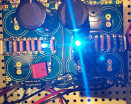
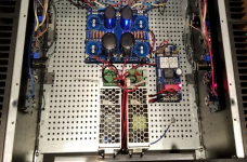
Sitting on floor and watching Pass-style blue bright LEDs on the power board, something hiding in the shadow, 14 resistors. Is that the problem? Two jumpers in. Turn on power, music flows. F4 sounded better. But I felt something still missing.
How Is It Sound? Little Disappointing!
After few hours monitoring and testing, hooked up my test gear, Marantz ND8006 as source, DIY M7 preamplifier, F4 with SMPS, and a pair sacrifice speakers. Repeat on/off test, no pop. The circuit works perfectly as designed.
When some familiar music collections played, I was disappointed. All music sounded dull. I though it was caused by the sacrifice speakers. After few hours and nothing bad happened, I changed my regular Harbeth C7ES back. It still sounded dull.
How Is It Sound? Improved a little
Sitting on floor and watching Pass-style blue bright LEDs on the power board, something hiding in the shadow, 14 resistors. Is that the problem? Two jumpers in. Turn on power, music flows. F4 sounded better. But I felt something still missing.
Attachments
How Is It Measured? No Big Difference.
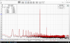
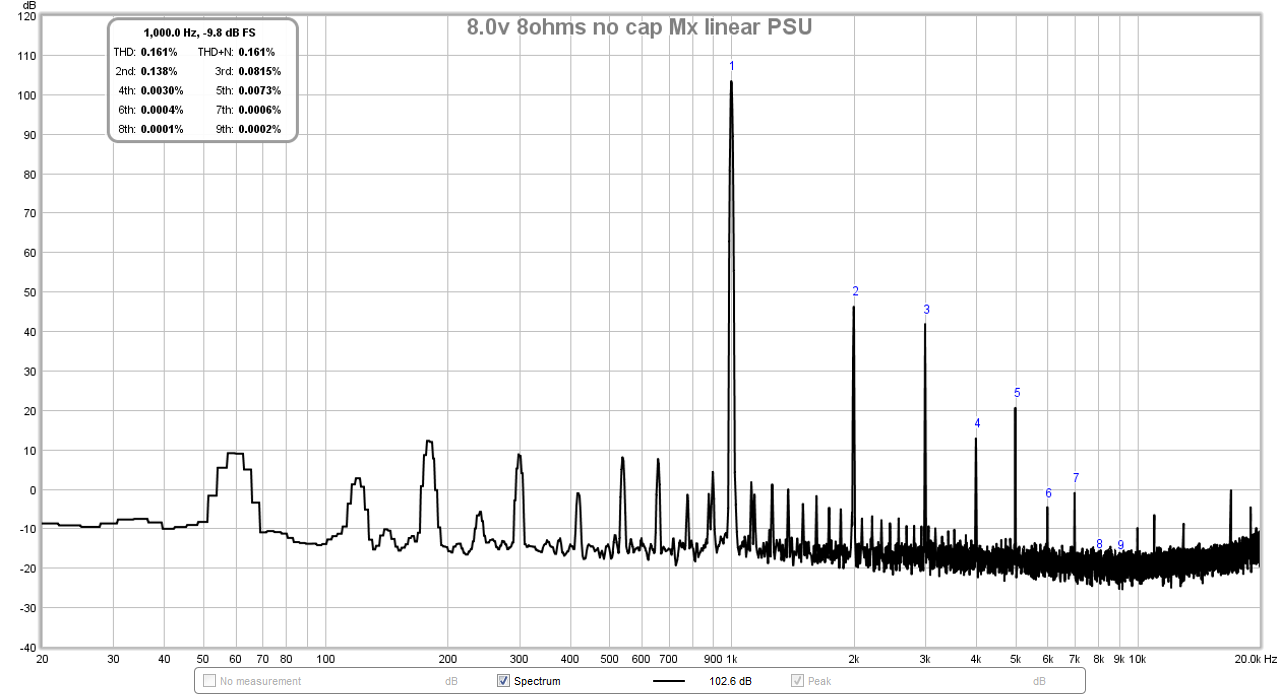
Beautiful F4, main 2nd harmony and very little 3rd harmony distortion. High order distortions are not visible. It can be seen the SMPS has even less interference from the power line.
Left traditional linear PS, 32VDC. Right SMPS at 24VDC
Beautiful F4, main 2nd harmony and very little 3rd harmony distortion. High order distortions are not visible. It can be seen the SMPS has even less interference from the power line.
Left traditional linear PS, 32VDC. Right SMPS at 24VDC
Attachments
Last edited:
How Is It Sound? Improved Somehow Again but Felt Never as Good as Before
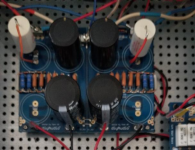
As a believer of big capacitors, two more 22000uF capacitors are back. The SMPS can still start. 2x10u Mundorf MKP film capacitors added to the capacitors army.
The sound improved somehow but felt still not as good as before.
There are so many discussions about to use or not to use regulated power supply for power amplifiers. It is the general subjective feeling (majority of diyers) that amplifiers with regulated power supply sound less interested, excited and vivid. My subjective feeling is the SMPS can not match my previous Hammond 625VA 1182T24(=/-32VDC). It might be just the much larger transformer and much higher supply voltage. I don’t know.
What Is the Cost?
The new and good brand industrial SMPS are expensive, like the one I used, it costs 150US$ per piece. Fortunately, every 5-7 years, millions and millions SMPS retire from the manufacturing industry and end up on Ebay, electrical flea markets and even junk yards! There won’t be short supply for our Diyers. We just have to looking for some good ones. I bought these two on Ebay for less than 40US$/Unit. They are 75-80% new. Plus two good sounding capacitors, the total number of the setup is 100US$. Comparing Antek 300VA toroidal and bridge rectifiers and capacitors, the price is about same.
How Big Should be used?
Generally for FW amplifier with 300W transformer, two 24VDC/7.5A SMPS(150W) should be sufficient.
Further Improvement?
The big capacitors behind SMPS lost its filtering function. But it might be still needed as an energy reservoir. Industrial SMPS have limited capability to dump big current at once.
For peace of mind, add a high frequency filter.
A even bigger SMPS with 10A output capacity with more capacitors but more cost.
SMPS specialized for audio.
What else can be done to improve the sound?
Attachments
Two builders have tried a different SMPS that was designed to power Class A audio amplifiers. One of those was posted in Pictures of your diy Pass amplifier.
It might be worth checking that one out if you still want to experiment.
It might be worth checking that one out if you still want to experiment.
Beautiful F4, main 2nd harmony and very little 3rd harmony distortion. High order distortions are not visible. It can be seen the SMPS has even less interference from the power line.
Left traditional linear PS, 32VDC. Right SMPS at 24VDC
I would say that the linear PSU has what I call the “forest of noise” problem and the SMPS has a much lower noise baseline. You may have a ground loop somewhere with the 60Hz peak, but overall noise baseline is much improved.
M2 with linear CRC PSU:
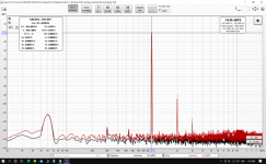
M2 with two 24v x 5A SMPS in series:
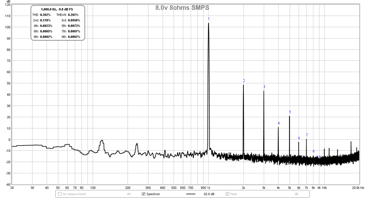
I observed the same reduction in noise when I used two LED 24v 5A bricks in series for an M2 amp. The forest of noise went away. To really clean up that forest of noise in a linear PSU, I have only been able to achieve using a CRC and capacitance multiplier based PSU - same as what TA used on his VFET amp. With that PSU, I essentially got a quiet flat noise floor - here is a recent measurement from one of my amps. The noise floor of a good SMPS is just as smooth and low.
Last edited:
- Home
- Amplifiers
- Pass Labs
- Mod DIY F4 with Industrial SMPS