")
 and I need a forklift
 xrk971, I was asking about the input capacitence of the amp. I believe Nelson mentioned in his old Build a Mosfet Citation article that when using a Mosfet as a source follower the effective input impedance was much lower than the raw figure so I wonder if the same would hold true of this power jfet.
Over in the SuSyLu thread, Mbrennwa did an experiment and found that adding a pot to the gate to ground resistor of the JFET will allow us to adjust the Vgs independently of the bias current set by the cascode trim pot. This is helpful to allow essentially, almost any LU1014D to be used in the optimal linear region. Thanks, Mbrennwa!
JPS64 will add this optional feature as soon as he has some time to modify the layout. I would probably add a 10uF cap on the wiper of the pot to reduce any noise from the rail contaminating the input. If we are trying to put about 0.5v DC onto the gate from 28v rail, a 50k resistor to the rail and a 10k pot in series with 50k to ground with the wiper set near 6k would work well to give the proper dynamic range and sensitivity.
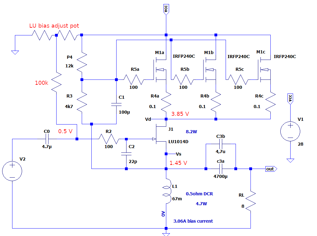
JPS64 will add this optional feature as soon as he has some time to modify the layout. I would probably add a 10uF cap on the wiper of the pot to reduce any noise from the rail contaminating the input. If we are trying to put about 0.5v DC onto the gate from 28v rail, a 50k resistor to the rail and a 10k pot in series with 50k to ground with the wiper set near 6k would work well to give the proper dynamic range and sensitivity.
Last edited:
LuFoLite
I was looking at the DeLite amp by Mr Pass today and it gave me the idea to swap the power resistor on my LuFo Lite headphone (or fleawatt) amp with a light bulb. I was at the grocery store today and was down the home cleaners and lightbulb aisle. I saw some GE T2.5 12v 20w halogen bulbs. I said “why not”?
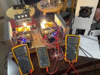
I replaced R3 with a halogen bulb and made the rail voltage 20.0v:
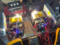
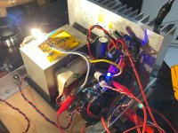
Once home, I promptly swapped out the 1.5ohm 10w resistors for the bulbs. I had a 12v SMPS supply which gave me 8v after the 4v drop in a cap Mx. I swapped out for a 24v 60w SMPS and fired it up. The cap multiplier has a nice slow rise and brought it up to 20v rail as predicted. About 12.9v at the JFET source and 0.9v drop across the MOT for exactly 12v at the lightbulb! It’s glowing brightly - we all know what a 12v countertop halogen lamp looks like. Nice not to need a heatsink for the light bulb resistor which I guess is dissipating about 20w. The LU1014D is dissipating about 11.4w.
I am using two separate SMPS bricks (Meanwell 24v, 2.6A). Listening with a small 3FE22 90dB full range speaker in a small test enclosure with an iphone as source. Makes music and is quiet. No hum. Will listen more critically with headphones next. Or maybe with some real speakers and big high swinging preamp.
Vital stats: 20v rail, 1.63A bias current, 12.9v source voltage, 12.0v at the lightbulb.
I was looking at the DeLite amp by Mr Pass today and it gave me the idea to swap the power resistor on my LuFo Lite headphone (or fleawatt) amp with a light bulb. I was at the grocery store today and was down the home cleaners and lightbulb aisle. I saw some GE T2.5 12v 20w halogen bulbs. I said “why not”?
I replaced R3 with a halogen bulb and made the rail voltage 20.0v:
Once home, I promptly swapped out the 1.5ohm 10w resistors for the bulbs. I had a 12v SMPS supply which gave me 8v after the 4v drop in a cap Mx. I swapped out for a 24v 60w SMPS and fired it up. The cap multiplier has a nice slow rise and brought it up to 20v rail as predicted. About 12.9v at the JFET source and 0.9v drop across the MOT for exactly 12v at the lightbulb! It’s glowing brightly - we all know what a 12v countertop halogen lamp looks like. Nice not to need a heatsink for the light bulb resistor which I guess is dissipating about 20w. The LU1014D is dissipating about 11.4w.
I am using two separate SMPS bricks (Meanwell 24v, 2.6A). Listening with a small 3FE22 90dB full range speaker in a small test enclosure with an iphone as source. Makes music and is quiet. No hum. Will listen more critically with headphones next. Or maybe with some real speakers and big high swinging preamp.
Vital stats: 20v rail, 1.63A bias current, 12.9v source voltage, 12.0v at the lightbulb.
Attachments
I think I am ready to build this on a proper PCB now and place the T2.5 halogen bulb right on X135 connector pad. It would be good to use a socket there so that the bulb can be periodically replaced.
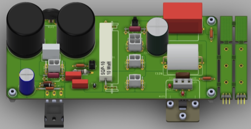
Now that the PCB will work as is, without any mods I’ll release the Gerbers for anyone wishing to make the LuFoLite in the thread here.
Now that the PCB will work as is, without any mods I’ll release the Gerbers for anyone wishing to make the LuFoLite in the thread here.
Last edited:
Here is the latest revision to the LuFo amp PCB with latest mod suggested by Mbrennwa for adjustment of the LU1014D Vds. That mod can be bypassed by adding a jumper across C184/194 to short it to ground and DNP both R184/194 and R183/193.
All manufacturing files are included below (BOM in Excel fomat, stuffing diagrams and schematic in PDF, and Gerber files).
A big thank you to JPS64 for this superb layout!
For those of you who do not want to order your own PCB's (as these are larger PCBs, they can be expensive if all you need is a pair), there is a GB signup sheet here.
Attachments
-
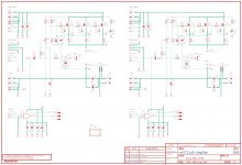 LUFO-Amp-Sch-v02-JFET-bias-mod.jpg669.3 KB · Views: 455
 -
LuFo-Gerbers-Rev02b-Nov-02-2021.zip1.2 MB · Views: 186
-
LUFO-AMP_PBA-BOT_002.pdf23.8 KB · Views: 194
-
LUFO-AMP_PBA-TOP_002.pdf68.3 KB · Views: 200
-
LuFo-BOM-Rev02b-Nov-02-2021.zip26.3 KB · Views: 190
-
LUFO-AMP_SCH_002.pdf128.8 KB · Views: 251
Last edited:
The manufacturing files (Schematics, BOM, Stuffing Diagrams, Gerber Files) for the OPA454 HV opamp front end fir the LuFo/SuSyLu can be found here.
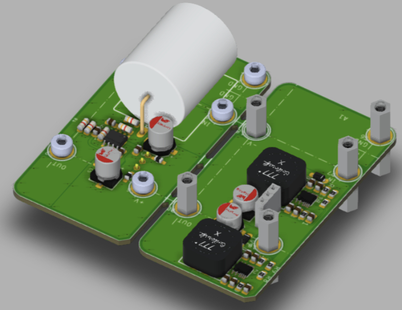
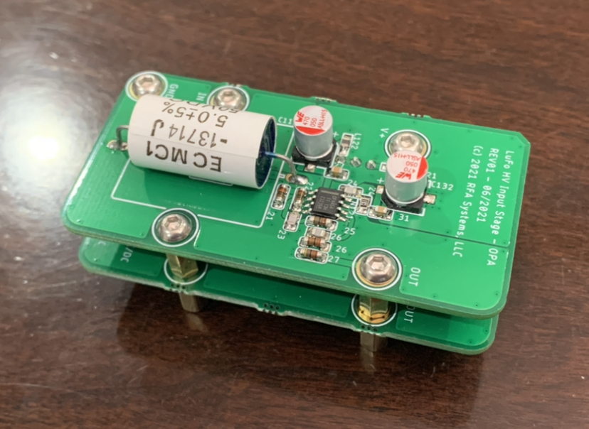
This front end board has its own +/-35v power supply that is fed from a single rail from 12v to 30v. This can be provided through a separate external power supply connection on the LuFo PCB or by adding a jumper between the +28v rail to the power input.
The OPA454 is scarce and hard to find at present, however, an OPA445 can also be used - just do not populate R124 and C124.
Last edited:
- Home
- Amplifiers
- Pass Labs
- LuFo Amp - 39w SE Class A from 28v Rail