Big Cal
One and Only
Altec Lover
Man who is single-handedly moderating Da Pub all these years, being absolutely able to keep Pubbers on the leash, without them wallowing and crying as spoiled brats (which they are)

Cal, as in Cal Weldon? Speaker guy who has taught so many using so few words regarding speakers? Moderator who walks softly and carries a big speaker? Knowledge base and all around good Canadian guy?
That Cal?
Barely know him.

He is a great guy though...
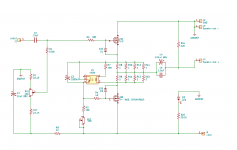
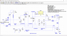
I have been playing with a QA402. Figured it would apply to this thread.
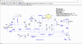
Attached is the schematic as tested.
The THD vs Power are at three different VDS voltages. You can dial up the second harmonic or not. I found 30 VDS was nice until you wanted large scale classical music, then the distortion was not as nice. 35Vds less sugar but better balance.
Attached is the schematic as tested.
The THD vs Power are at three different VDS voltages. You can dial up the second harmonic or not. I found 30 VDS was nice until you wanted large scale classical music, then the distortion was not as nice. 35Vds less sugar but better balance.
Attachments
-
 DIY Follower Sch.PNG13.8 KB · Views: 1,025
 -
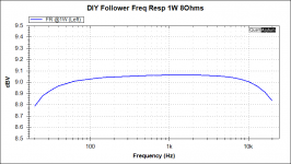 DIY Follower Freq.png17 KB · Views: 1,000
 -
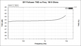 DIY Follower THD vs Freq.png16.9 KB · Views: 849
 -
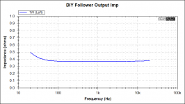 DIY Follower Imp.png17 KB · Views: 746
 -
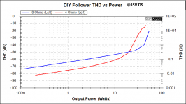 DIY Follower THD Vs Power 35vDS.png21.5 KB · Views: 739
 -
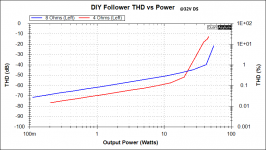 DIY Follower THD Vs Power 32vDS.png20.7 KB · Views: 279
 -
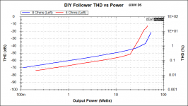 DIY Follower THD Vs Power 30vDS.png20.7 KB · Views: 409

Well, I finally got around to doing some work on this project. I took apart the right channel of the BAF2015 THF-51S amplifier and re-did the CLC power supply for V- by moving Hammond 159ZJ choke to the negative side of the supply. Tested successfully with a dim bulb tester without load and with resistor load, and then with tester removed.
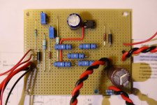
Next up was planning the layout for the circuit board. Because I was really happy with the stripboard channels that I did for my F2J, I decided to go with strip board for this project too. I roughed out the layout with pencil on paper, and then refined it on LTSpice. One big advantage of doing the layout on LTSpice was that I could run the simulation to check for mistakes.
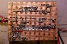
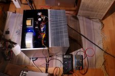
I have now finished the right channel circuit board, and after checking the finished board multiple times, I tested the CCS. I connected my 8 Ohm amplifier test load to the CCS as a load. The first power-up was with a dim bulb tester in place. No issues so I removed the tester and applied full AC.
Again no issues, except I may have to tweak the CCS as the maximum current was 2.87A with the 8 Ohm resistor bank as a test load. I will make a resistor adjustment if required once I install the THF-51S.
So the next step is to connect the board to the THF-51S.
Next up was planning the layout for the circuit board. Because I was really happy with the stripboard channels that I did for my F2J, I decided to go with strip board for this project too. I roughed out the layout with pencil on paper, and then refined it on LTSpice. One big advantage of doing the layout on LTSpice was that I could run the simulation to check for mistakes.
I have now finished the right channel circuit board, and after checking the finished board multiple times, I tested the CCS. I connected my 8 Ohm amplifier test load to the CCS as a load. The first power-up was with a dim bulb tester in place. No issues so I removed the tester and applied full AC.
Again no issues, except I may have to tweak the CCS as the maximum current was 2.87A with the 8 Ohm resistor bank as a test load. I will make a resistor adjustment if required once I install the THF-51S.
So the next step is to connect the board to the THF-51S.
Attachments
-
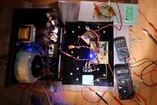 THF-51S Mu Follower Right Channel CCS Full Power Test1.jpg612.8 KB · Views: 484
 -
 THF-51S Mu Follower Right Channel CCS First Power-up1.jpg545.8 KB · Views: 381
 -
 THF-51S Mu Follower Right Channel Board - Back1.jpg756.6 KB · Views: 322
 -
 THF-51S Mu Follower Right Channel Board - Front1.jpg405 KB · Views: 551
 -
 THF-51S Mu Follower Right Channel Layout.png113.5 KB · Views: 615
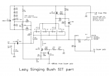
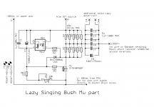
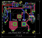
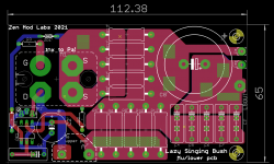
I've send some files to codyt ( he was poking me badly), even if I really wasn't much interested in this variation
psbs are ordered, need just to check stability of JFet cascode
besides that, everything else trivial
as previously - my intention is that SIT gate must be firmly grabbed by ball$
here, you can try to include some of it in your build
psbs are ordered, need just to check stability of JFet cascode
besides that, everything else trivial
as previously - my intention is that SIT gate must be firmly grabbed by ball$
here, you can try to include some of it in your build
Attachments
ZM, I don't think I'll need an input buffer. I'm going to build a KP926B voltage gain stage to put in front of this amp and I believe it will have low enough output impedance, and hopefully a lot of voltage swing.
The THF-51S that I am using behaved in the previous iteration of the amp in common source mode so I don't believe gate leakage current is a problem with them. However, I am going to reduce the overall resistance of the voltage divider for the bias voltage so that there will be more current in the voltage divider.
Cody, I hope to get the right channel up and running today or tomorrow, barring any problems. Then for some testing and listening with one channel.
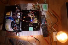
The right channel is assembled and it works. No matter how much I check, double check, and triple check, it was still with trepidation when I powered up the completed amplifier for the first time. Will it work or will it smoke? And that was with a dim bulb tester.
But it fired up with no smoke and the trim pots adjusted the voltage and current as expected. I do need to change a resistor in the CCS to get the current up to 3A and higher though. It currently maxes out at 2.78A. So the 5K resistor in series with the 10K pot will be changed to 3K.
A strange thing was that the power supply under power measured 65.8V. When it was powering the BAF2015 THF-51S common source version, the power supply under load measured 62.5V. With the higher power supply voltage, I can run the THF-51S at higher voltage, perhaps with better performance.
So I connected my ACP+, tuner, and test speaker to the amp and music played.
Tomorrow it's measurements.
Attachments
Thanks for the tip, ZM. I took the easy way out and paralleled a resistor with the rail to gate resistor. That way I did not have to remove the board to get to its back side. I'll remember your tip for future use.
jwjarch, Yes, that's a Dynaco A25, my first speaker bought 47 years ago for my university dorm system, back when most wanted a stereo system. That was before home computers and cell phones, or even cordless home phones, and calculators were only four function. And a diy amplifier was a Dynakit, which I also bought and built. How times have changed!
jwjarch, Yes, that's a Dynaco A25, my first speaker bought 47 years ago for my university dorm system, back when most wanted a stereo system. That was before home computers and cell phones, or even cordless home phones, and calculators were only four function. And a diy amplifier was a Dynakit, which I also bought and built. How times have changed!
Ben, my father bought a few pairs of those back in the day. I stole a pair for my bedroom and listened to them all through high school. I have to say, those SEAS woofers had impressive bass for a slot vented enclosure. He also built a Dynaco ST-120. I guess the DIY audio bug has always run in the genes in my family.
Regarding your supply voltage, do you foresee the increase in CCS current dropping the supply a bit more? Also curious why it jumped up so much between amplifier designs.
Regarding your supply voltage, do you foresee the increase in CCS current dropping the supply a bit more? Also curious why it jumped up so much between amplifier designs.
My Dynakit was sand, a SCA80Q. Later on I got into diy tubes, mainly single ended triodes. That may be the reason why I'm attracted to SITs. I started with the diyAudio Sony VFET amp in 2017 and here I am.
I was baffled by the increase in supply voltage since the two designs are similar with the main difference being common source versus common drain, but that shouldn't change the power usage and affect the supply voltage. The BAF2015 amp was drawing even less current at 2.5A. Since I still have the left channel intact, I just measured the supply voltage and it was over 65V. So the reason must be that the AC line voltage is higher. That does make sense because I mainly used the amps in the winter when electricity demand in Vancouver is higher due to the cold temperatures, so the line voltage was lower. It is summer now so the line voltage is higher. I just measured 121.8VAC. I have measured as low as 115VAC in the winter.
Since I will be using this new amp in the winter, I will have to take the line voltage into consideration. I will have to adjust it a bit in the winter to suit the lower line voltage.
- Home
- Amplifiers
- Pass Labs
- Single Ended Tokin SIT THF-51S Common Drain Mu Follower Amplifier, 45W?