OK, so I added a quiet-running fan at the back of the case (the existing hole suits a computer case standard case fan) that runs off a seperate 12VDC supply.
Just tried a test run and its taking at least between 10-15 deg C heat off the devices. So based on a test run of about half an hour (and depending on laser thermometer accuracy) the VFET devices are running at about 33-35 deg C each side.
Im pretty happy with that result.
I've also bypassed the speaker output caps and have some Mundorf caps coming in the mail to replace all 4 x .33uF poly input caps.
Once I've done all that, the only thing left to do (apart from sitting down and actually listening to the amp!) is to find a suitable trafo to install a linear PS, as I have room in the case to do that.
I have now found 3 x 2SJ28 VFETs. A KF-33 (which I will try using to replace the one that has "flicker noise"). A KE-33 and a JA-33.
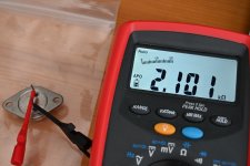
Both KF-33 and KE-33 validates as a JFET when I test it using a PEAK DCA75 tester but JA-33 shows up as "shorted".
Using another tester the two working JFETs shows up as two diodes while the JA-33 shows up as two resistors.
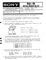
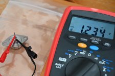
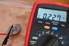
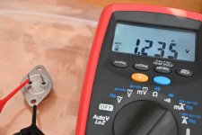
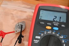
I made a few more measurements on JA-33 using DMM using method written by Sony (attached).
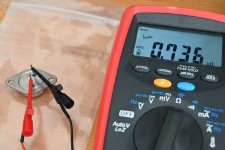
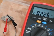
Also my measurements are attached where filename indicates which measurement. Ohm measurements and diode measurement in both directions.
The measurements shows diode function in both directions for e.g. the G-S junction. Should a G-S junction on a JA-33 beak down if more than 2V is applied in "reverse direction"?
Or would you also judge this JA-33 as not working based on the measurements?
Both KF-33 and KE-33 validates as a JFET when I test it using a PEAK DCA75 tester but JA-33 shows up as "shorted".
Using another tester the two working JFETs shows up as two diodes while the JA-33 shows up as two resistors.
I made a few more measurements on JA-33 using DMM using method written by Sony (attached).
Also my measurements are attached where filename indicates which measurement. Ohm measurements and diode measurement in both directions.
The measurements shows diode function in both directions for e.g. the G-S junction. Should a G-S junction on a JA-33 beak down if more than 2V is applied in "reverse direction"?
Or would you also judge this JA-33 as not working based on the measurements?
Attachments
-
 sony_service_bulleting_62.jpg535.6 KB · Views: 192
 -
 JA-33-G-S-ohm.JPG558.9 KB · Views: 41
 -
 JA-33-S-G-ohm.JPG557.9 KB · Views: 47
 -
 JA-33-S-G-diode.JPG563.1 KB · Views: 46
 -
 JA-33-G-S-diode.JPG562.6 KB · Views: 175
 -
 JA-33-D-G-diode.JPG530 KB · Views: 178
 -
 JA-33-G-D-diode.JPG541.5 KB · Views: 184
 -
 JA-33-S-D-ohm.JPG540.4 KB · Views: 187
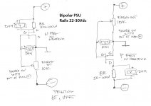
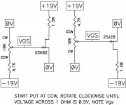
Testing depletion parts
This will require that I find a large heat sink for TO-3?
How would such a "test-schematic" look like for a P-channel?
Attachments
Last edited:
Is there a significant electrical difference between KF, KE and JA-33 so a simple tester could be "fouled"?
I have tried to find out what the exact electrical difference is between the XX-33 versions but I have not succeeded to find a datasheet that specifies this.
its already told that these are rankings simply by biasing voltage
Yes, and I can probably find a cheap heatsink 2nd hand.....and drill some holes.
Did they produce them in large batches and then depending on Vgs they where stamped KF, KE, JA etc? .....like JFET grades?
The JA-33 has a faint red "F" written on it......I wonder what that could mean......
Did they produce them in large batches and then depending on Vgs they where stamped KF, KE, JA etc? .....like JFET grades?
The JA-33 has a faint red "F" written on it......I wonder what that could mean......
This will require that I find a large heat sink for TO-3?
How would such a "test-schematic" look like for a P-channel?
Official schematic made by Mr. Pass
Have a good time
")
Attachments
I have some mica TO-3 isolators and also the white "grease".
A seller wants to sell 3 of these old boards......for not very much.
I only need one.....but forced to get all 3.
A lot of TO-3 holes......size of heatsink looks sufficient?
Should be possible to free heatsink from PCB and keep that and trash the "other stuff". Maybe a couple of the power resistors can be used also.
It look really old and "outdated".
Attachments
- Home
- Amplifiers
- Pass Labs
- DIY Sony VFET Builders thread