so i found a Sony TA 4650 (vfet amp) local for about $400 bucks. Very clean and in working order and no upgrades. whats everybody though get it strip out the chips and build a second amp or just use it or sit on it for a bit and see what happens. dose anyone have another ideas.
I would do the recommended service mods in the Dutch service schedule, do the balanced voltage board mods, replace the suicide diodes, clean and remount the vfets and then use as is. They are a super sounding amp and look very stylish and unique. Getting very hard to find in good condition these days.
As chips, the J28/K82 are optimized around 8 ohm loads. The J18 and K60 more
like 16 ohms, so instead of a CCS for bias we will likely use a mu follower to make
them think an 8 ohm load is 16 ohms.
Hi Nelson,
For the next build, do the sk60s or sj18s need to be of equal rank or will any of the same sex do?
Many thanks,
Jon
With all this talk of SJs and SKs this seems a good thread to ask!
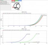
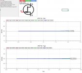
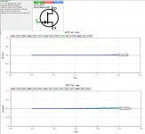
I bought a TA-5650 to restore and it ended up missing a 2SK60 VFET, I've found some replacement 2SK60s and the 2SJ18s to go with and thought I'd buy a couple spare in case of issues / to also build the new VFET amp.
Not that I really know what I'm doing with a curve tester, but I've curve tested all the existing VFETs and now the new ones. From the new ones, I have 2 which don't graph anything like the others - what do you think, is it fair to assume they're dead? The lack of curves doesn't seem promising")
I've attached an existing one as a comparison....
I bought a TA-5650 to restore and it ended up missing a 2SK60 VFET, I've found some replacement 2SK60s and the 2SJ18s to go with and thought I'd buy a couple spare in case of issues / to also build the new VFET amp.
Not that I really know what I'm doing with a curve tester, but I've curve tested all the existing VFETs and now the new ones. From the new ones, I have 2 which don't graph anything like the others - what do you think, is it fair to assume they're dead? The lack of curves doesn't seem promising
I've attached an existing one as a comparison....
Attachments
Hi Nelson are 2SK82 KD-33 good for kit ?As chips, the J28/K82 are optimized around 8 ohm loads. The J18 and K60 more
like 16 ohms, so instead of a CCS for bias we will likely use a mu follower to make
them think an 8 ohm load is 16 ohms.
I am not Nelson, but the 2SK82 are good for the N-channel kit, yes.
https://www.diyaudio.com/forums/att...82-diy-sony-vfet-pt-1-a-diy-sony-vfet-pt2-pdf
https://www.diyaudio.com/forums/att...82-diy-sony-vfet-pt-1-a-diy-sony-vfet-pt2-pdf
Last edited:
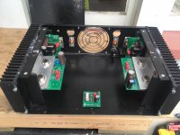
In the interests of publicly posting my build for this amp - I am finally making progress. I couldnt afford the case the project goes with, I also tried (twice) to purchase a cheaper case from Aliexpress, but had a terrible time with both sellers first telling me the case I wanted was in stock, and then it transpiring that it actually wasnt.....leading to disputes, cancellations etc.
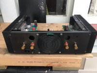
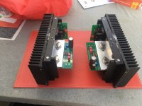
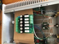
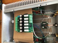
I took the "cheapo" option of buying an existing PA amp with large heatsinks, and fitting the project in that. This turned out to be tricky, as it transpired that the heatsinks on each side were actually in 2 seperate pieces, and some internal mounting fins prevented these kits from properly fitting. A couple of days of grinding/filing later, and I could mount the modules on each side. I am just hoping that the thermal bond between both the modules to the heatsink, and between each part of the heatsink on each side, works well.
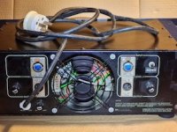
I will keep a good eye of device temperature. If I run into issues, I can always also mount a fan at the back of the case. If that doesnt work, I may need to try a different case.
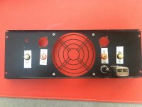
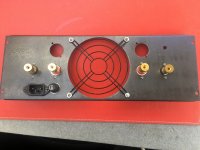
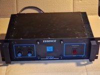
Heres my progress on assembling the case, its all going well so far. The front panel is beyond repair, as it had numerous holes for volume control, indicators, bolts for the main trafo, etc. So I will be covering that with a snazzy piece of coloured perspex instead.
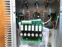
Now Im at this point with the case assembly, I can start the point-to-point wiring between each module. Im leaving a lot of room in the middle of the case in case I decide to install a linear powersupply with a large torroidal at a later stage, instead of the Meanwell brick.
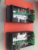
I have a couple of cool RCA recessed metal panel connectors to go into the two rear top holes. I also have a large Nichicon Super Through cap that I will solder into the reverse side of the output module (hanging down) as otherwise it will be mounted too close to the heatsink if I mount on the topside (being a larger diameter cap than the ones supplied with the kit....)
I took the "cheapo" option of buying an existing PA amp with large heatsinks, and fitting the project in that. This turned out to be tricky, as it transpired that the heatsinks on each side were actually in 2 seperate pieces, and some internal mounting fins prevented these kits from properly fitting. A couple of days of grinding/filing later, and I could mount the modules on each side. I am just hoping that the thermal bond between both the modules to the heatsink, and between each part of the heatsink on each side, works well.
I will keep a good eye of device temperature. If I run into issues, I can always also mount a fan at the back of the case. If that doesnt work, I may need to try a different case.
Heres my progress on assembling the case, its all going well so far. The front panel is beyond repair, as it had numerous holes for volume control, indicators, bolts for the main trafo, etc. So I will be covering that with a snazzy piece of coloured perspex instead.
Now Im at this point with the case assembly, I can start the point-to-point wiring between each module. Im leaving a lot of room in the middle of the case in case I decide to install a linear powersupply with a large torroidal at a later stage, instead of the Meanwell brick.
I have a couple of cool RCA recessed metal panel connectors to go into the two rear top holes. I also have a large Nichicon Super Through cap that I will solder into the reverse side of the output module (hanging down) as otherwise it will be mounted too close to the heatsink if I mount on the topside (being a larger diameter cap than the ones supplied with the kit....)
Attachments
Last edited:
Yes, the heatsinks on the custom VFET chassis just get warm to the touch. The best thing to to with the smaller heatsinks will be to make sure both surfaces are flat (carefully grind with a fine stone if necessary). Then use a very good thermal grease such as Arctic Silver, which is the kind included with the kit.
Thanks all. The heatsink area on my L'amp amplifier is a little smaller than this one - however of course there is only one device in that one, and this kit has two hot devices that need heatsinking.
Another member coincidentally lives close to me in Christchurch NZ, and he built this kit with the proper case. I saw and heard his build, while the heatsinks are larger on the proper case, they are about half the depth and also thinner overall. While that probably allows for more efficient heat dissipation, the heatsinks on my case are chunkier in general. So, heres hoping....
I will wire it up and fire it up, but thinking if the devices get close to 70 deg C, then I'll have to consider using a fan next....
Test install of the Theseus-PSFilter Board for Sony P-Channel VFET Amps
I built my P-channel Vfet amp a month or so ago # 059 -- . For most of that time, I have been using an older, simple battery-powered headphone amp to feed the amp. Every time I turned on the headphone amp, I heard a loud THUMP from both speakers. The thump was even louder on power off.
About 2 weeks ago, I finished my Amp Camp Preamp/headphone amp (ACP+). It did not take long for me to whip the ioutput leads off of the tube amp and plug in the ACP+.
Both the Vfet amp and the ACP+ sound great, match together really well in my opinion, but I still get a thump on power switch transitions.
Then a week or so ago, along comes Mark Johnson with an offer to test drive one of his "new and improved" power supply filter boards. The design is an improved version of the improved version of the filter board in the N-channel kits. Some others have already swapped out the filter board in their N-channel Vfet amps -- see DIY Sony Vfet Pt2 N-channel Build post #461 and post #528.
I'm about 3/4 finished with the swap out but I'd better quit before I start "taking stupid" and making mistakes (like, trying to remember which wire, green or white, I connected to the + lead of the LED....of course I did not check that minor fact before I unsoldered the LED leads from the old filter board...)
So hopefully I'll get to power up this rig and test drive it tomorrow -- and will find nothing but quiet music with no thumps.
Thanks again Mark for letting me try out this new, new power supply filter board
HappyJack
Attachments
- Home
- Amplifiers
- Pass Labs
- DIY Sony VFET Builders thread