I’m sure I’ve read the answer to this in one of the Vfet threads but can’t find it.
I grabbed some of the Tokin sit in anticipation of the future kits. Will these also be using the same FE boards? And any idea if they will come with the same FE as the VFET amps? Just trying to figure out whether to preorder as suggested for the future releases.
I grabbed some of the Tokin sit in anticipation of the future kits. Will these also be using the same FE boards? And any idea if they will come with the same FE as the VFET amps? Just trying to figure out whether to preorder as suggested for the future releases.
I believe Nelson has several new designs up his sleeve that will benefit from these, all in good time. Now don't start bugging him every five minutes.
Nelson and I briefly talked about some new boards that have not yet appeared, which are compatible with all of today's VFET boards. It was at the end of the Burning Amp 2021 Zoom meeting ... I guess you'd call it the continuation / bull session, of people who didn't exit the video conference at the official ending when they said thank you and ceased recording. A few minutes later, maybe 3:15 Pacific or so.
If my memory is correct, there have been two Dreadnought builders who have shared their listening impressions and opinions about its sonics. One of the Dreadnought builds was completely "stock" (exactly following the schematics & parts lists attached to post #1 of this thread) and the other had a relatively large number of parts-swaps; let's call that super-personalized & super-modified.
.
.
.
Follow your heart.
Want exclusivity? I mean, incredibly rare and impossible to find Front End cards? Locate somebody who qualifies to own the Relentless cards (post #19 of this thread) and barter with them. You may have to "payer par le nez" as the French might say.
Is anyone measured the amp distortion to determine a more suitable card? I am thinking about addressing the high-ish low freq distortion that NP attributes to the transformer.
If there is a weak spot in the VFET the amp (FOR ME) is a little bit of sloppiness in the base that seems to match the distortion vs frequency. Although I grew to like it in bad recordings, I would like to know which card may potentially address that.
Last edited:
The Edcor transformers used by the kit front end and two of the later designs by Mark J. actually have good bass response. They are not the limiting factor that one might experience with their VFET amp. The simplest way to get a sense of what the amp is capable of is to start by adding separate 1000 uF to 1500 uF capacitors to the power rail of each OS board.
To hear what the amp is fully capable of requires replacing the kit SMPS supply with a dedicated external linear power supply. Dual-mono is necessary.
To hear what the amp is fully capable of requires replacing the kit SMPS supply with a dedicated external linear power supply. Dual-mono is necessary.
Euroblock screw type 2 pin connectors are included to assist in swapping out the front end cards.
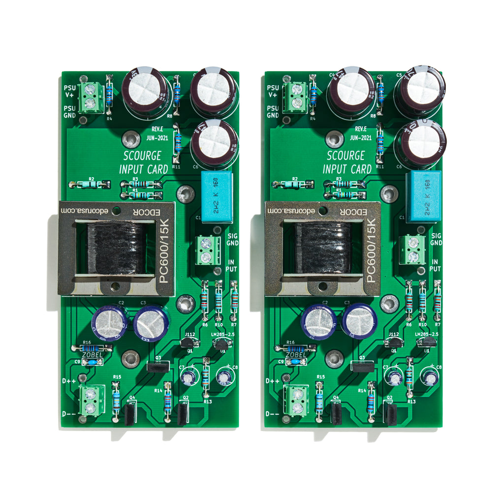
You can clearly see them on the photographs in the diyAudio Store. I've linked to the Store's Scourge photo below; click on the image to see it full size and undistorted.
Connectors are located at top left ("eleven o'clock"), center right ("three o'clock"), and bottom left ("seven o'clock"). On the boards in the photo, connectors are green plastic rectangles containing two shiny zinc metal screw heads.
edit- the photo reveals that the boards also include wire-to-board attachment holes, for those like ZM and NP who prefer I/O wires to be soldered instead. Use the connector or solder the wires, it's your choice, do it however you prefer!
Last edited:
The Edcor transformers used by the kit front end and two of the later designs by Mark J. actually have good bass response. They are not the limiting factor that one might experience with their VFET amp. The simplest way to get a sense of what the amp is capable of is to start by adding separate 1000 uF to 1500 uF capacitors to the power rail of each OS board.
To hear what the amp is fully capable of requires replacing the kit SMPS supply with a dedicated external linear power supply. Dual-mono is necessary.
I get the picture but I resist modifying the VFET amp as it is my best amp so far and I can't be w/o it. I am hoping Ludef will give me a chance to play with the points you mention. I take it 1000-1500uf is fully safe with the SMPS?
A few of us have already added 1500 uF to the power supply of each OS board without any issues with the kit SMPS. It may be possible to add more, as suggested by the supply filter board for the newer N-channel version of the VFET amp.
After I built the external linear PSU for my amp, I added an extra 30,000 uF to each channel inside the amp chassis. It makes quite a difference.
After I built the external linear PSU for my amp, I added an extra 30,000 uF to each channel inside the amp chassis. It makes quite a difference.
A few of us have already added 1500 uF to the power supply of each OS board without any issues with the kit SMPS. It may be possible to add more, as suggested by the supply filter board for the newer N-channel version of the VFET amp.
After I built the external linear PSU for my amp, I added an extra 30,000 uF to each channel inside the amp chassis. It makes quite a difference.
Your linear PS is outside? Did you keep the 4 pins connector? What about the switch? Do you have pics? thanks
Quote: I seem to recall reading it in the article by the distortion plots. Maybe I misinterpreted the statement.
Page 14 of the article.
OK, see where you come from. TBH, whereas the graph shows indeed some rising distorsion levels at lower frequencies, they are still quite low and in a very low frequency range where our ears are less sensitive. OK, they are there and measurable, but (IMHO) I doubt this reflects your bass slopiness as you call it.
For info, I went as far as bypassing the entire FE (and adjusting volume levels and reversing absolute polarity at my source to make things equal) to perform with / without comparison and found the difference to be... negligeable. And our bias (2 listeners) was clearly on "We must hear something now we got rid of all these parts" LOL.
In short: I don't think that the Edcors are the limiting factor regarding your listening impressions.
On the other hand, as posted by Tungstenaudio, playing with additional PS caps did a massive difference. Regarding bass, their response, sharpness and overall slam / speed, it moved these from acceptable (after 100h burn-it, as before the sound evolved a lot and was somewhat lacking in these criterias) to good or VG depending on the criteria.
Bottom line IME: play with the PS first to address your needs.
Having said all that, I am not saying that different FE cards wouldn't bring different sound flavours and, in fact, I mounted my V-FET from the start with screw connectors to enable all possible very quick tests re FE cards mods or swaps and PS tweaks to be performed. I love solid / soldered connections and hated screw connectors (especialy for music signals) and thought them provisory for testing only, but after some tests on another unit at similar voltage levels I must confess I can't hear them. Lessons learned, they might just stay, TBD.
Last but not least, for RAFAPOLIT, I didn't use any connectors at the OS. Reason being that you don't need connectors on 2 sides of a wire given that whatever you do the OS will obviously stay as that's the core of the amp (and if not the wires could still go with it). So I have soldered wires running from the OS boards... that run into connectors. Connectors are located on the FE cards (sound inputs and outputs... and PS) and at the filter boards level (all PS outputs). Some PS connectors are redundant but opened the door for access and convenience, I posted already which one are fundamental and which are optional. Just that enables all what you may want to play for...
For all the above, search function in this thread is your friend, by typing my name you will find pictures of all this and feedbacks... also some hints on how I did it to be sure the connectors where foolproof (different connectors for PS and signal, plus colour codes to mark the difference between ground and live).
I hope this helps
Claude
Last edited:
Claude,
you're probably right. I maybe reading too much into the distortion measurement and it's just a question of adding more peak current reserve near the point of use to strengthen the bass slam. I like the high efficiency, enviromentally friendly switching supply but maybe there is alot to be gained by making a few simple mods.
thanks
Check out posts #1400 and #1402 in the DIY Sony VFET Builders thread some of the initial description of how I built an external PSU for the amp. It was a long process, but very worthwhile. I eventually found the correct connector to replace both the male and female for the VFET amp DC inlet. I built my own umbilical cord from the external PSU to the amp chassis using the proper connector. The little DC filter board inside the amp was removed and replaced by a pair of terminal blocks. The little DC switch on the amp has been disconnected and the amp is now powered up by an AC inlet switch on the external PSU.
I have kept the original DC filter board intact, along with the original kit SMPS. Together, they are very handy to have for other development and testing activities.
I have kept the original DC filter board intact, along with the original kit SMPS. Together, they are very handy to have for other development and testing activities.
- Home
- Amplifiers
- Pass Labs
- Scourge, Bulwark, Marauder, Dreadnought "front end" cards for DIY VFET amp