These four Front End card designs: Scourge, Bulwark, Marauder, and Dreadnought ... are older than you might think. They were designed in August and September of 2020, to meet the best-guess specifications and VFET amp requirement estimates, at that time.
And, it's not a big shock: things have changed. I've been in several discussions with Nelson Pass about future versions of the amp, and those amps aren't going to exactly match our guesses of ten months ago. Surprise!
In particular, the Front End cards don't need to be simultaneously compatible with (PositiveSupply, NegativeGround) amp cards, AND (NegativeSupply, PositiveGround) amp cards, AND (BipolarSupply plus Ground) amp cards.
So there's a bunch of complexity on those Front End cards, that has turned out to be unnecessary. It's no longer needed. And so I have decided to revise each of the four Front End cards to get rid of the unnecessary components and eliminate the unnecessary circuitry. I made this decision after consulting with Nelson (of course), and he supports the change. The new revisions are already posted to this thread and are attached to post #1. You can view them right now.
These edits are quite simple
For those brave souls who have already ordered PCBs and/or ordered parts and/or begun stuffing and soldering: you will have an easy time implementing these changes. Some parts you simply cut off the board with flush-cutters. Other parts you simply flip the board upside down and solder a bare wire to short the part's two leads to each other -- you can either let the part remain on the board (shorted out), or cut it off after shorting. Either way works just as well, it's your choice.
The good news is: the new revision boards actually sound better than the original versions (!!). Why? Because it turns out that the revised circuits are now fed from lower-impedance power supplies. That means better PSRR, and less MeanWell switchmode crud injected into the audio circuits. I'm delighted that simpler is also better, in these cases.
I've also updated the offsite (non-diyAudio) web links in post #1, so they now point to offsite safety copies of the latest revision.
Anyone who has already started building the previous board revisions, and who is doubtful or confused: send me a PM and I'll try to answer your questions. Be sure to include a picture of your bare PCB, as proof that you're a real builder and not a time waster.
The changes are:
And, it's not a big shock: things have changed. I've been in several discussions with Nelson Pass about future versions of the amp, and those amps aren't going to exactly match our guesses of ten months ago. Surprise!
In particular, the Front End cards don't need to be simultaneously compatible with (PositiveSupply, NegativeGround) amp cards, AND (NegativeSupply, PositiveGround) amp cards, AND (BipolarSupply plus Ground) amp cards.
So there's a bunch of complexity on those Front End cards, that has turned out to be unnecessary. It's no longer needed. And so I have decided to revise each of the four Front End cards to get rid of the unnecessary components and eliminate the unnecessary circuitry. I made this decision after consulting with Nelson (of course), and he supports the change. The new revisions are already posted to this thread and are attached to post #1. You can view them right now.
These edits are quite simple
- A small number of components have been removed from each board
- In some cases, the removed component is replaced by a short circuit (a copper track on the PCB)
- In other cases, the removed component is not replaced at all. It becomes an open circuit
- Zero new components have been added. Not a single one.
- No component values (e.g. resistance) have been changed
- A couple of rows have been removed from each Detailed Parts List. No new rows have been added.
- The Mouser One-Click Shopping Carts have been revised to match the new Detailed Parts Lists.
- If and when PCBs + kits of all parts become available in the diyAudio Store, they will (of course) use these versions. The latest versions.
For those brave souls who have already ordered PCBs and/or ordered parts and/or begun stuffing and soldering: you will have an easy time implementing these changes. Some parts you simply cut off the board with flush-cutters. Other parts you simply flip the board upside down and solder a bare wire to short the part's two leads to each other -- you can either let the part remain on the board (shorted out), or cut it off after shorting. Either way works just as well, it's your choice.
The good news is: the new revision boards actually sound better than the original versions (!!). Why? Because it turns out that the revised circuits are now fed from lower-impedance power supplies. That means better PSRR, and less MeanWell switchmode crud injected into the audio circuits. I'm delighted that simpler is also better, in these cases.
I've also updated the offsite (non-diyAudio) web links in post #1, so they now point to offsite safety copies of the latest revision.
Anyone who has already started building the previous board revisions, and who is doubtful or confused: send me a PM and I'll try to answer your questions. Be sure to include a picture of your bare PCB, as proof that you're a real builder and not a time waster.
The changes are:
- Scourge: remove 4 diodes and remove 3 resistors
- Bulwark: remove 4 diodes and remove 3 resistors
- Marauder: remove 4 diodes
- Dreadnought: remove 4 diodes
Thanks for the update! I have a pair of Dreadnought boards in hand and am waiting for the parts to arrive from Mouser. I also ordered the Edcor transformers needed to build a pair of Bulwark boards.
Interestingly enough, I had already decided to make the changes that you describe. You know that’s how I roll.
Interestingly enough, I had already decided to make the changes that you describe. You know that’s how I roll.
I am impressed...
Although in reality this is 'just' a forum with 'only' enthousiasts - and not a company with customers - the only words that come to my mind are: this is what I call service.
In that case, for a community... for us. Well done, Sir!
Thanks for all this, again... all your developments are very well documented and I can only imagine the time all this and the rest require, just to make it easier to... all of us. Every single case has been taken care of and has been documented: chapeau!
Claude
In what is undoubtedly another unforeseen circumstance, the KSA1220A PNP transistors used in some of the new front end cards are now showing a worldwide shortage. The only hits seem to be coming from dodgy vendors referred by Octopart. Even an ostensibly valid vendor such as Kynix demands one open a new account, then submit a "request for quote," rather than add the parts to the shopping cart. This tells me the no one really has those parts in stock. Mouser no longer lists them as a stocked item, where they previously required a minimum order of 2000 pieces.
I happen to have a few left from previous buys, but only enough to supply my Dreadnought build. We will need to determine a suitable replacement for those who are interested in trying some of the new alternate front end cards for the Sony VFET amps, both P-type and the upcoming N-type.
Back in the day, before all the cool kidz started using the KSA1220A and its complement the KSC2690A, there were other parts in widespread use. These were the BD140 and BD139. Same package and pinout, very similar specifications. The Toshiba TTC004B and TTA004B look like very good options. Even the MJE15031 and MJE15030 might be pressed into use, given consideration for their reversed pinout.
Some guidance for suitable replacements would be much appreciated. Those who know me will expect a build using disavowed parts after some amount of time, but not everybody swings that way.
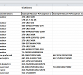
The latest revision (June 2021) of the Detailed Parts Lists, includes a suggested alternate part for the KSA and for the KSC medium power devices. Open the Detailed Parts List then check the "option 2" value, which is in Column L.
top of spreadsheet shown below
_
top of spreadsheet shown below
_
Attachments
This is great news. Does this mean there is a possibility of the store offering these additional input stages as kits in the future?Fortunately I have a large supply of those transistors and have set some aside for this project.

That would be great news indeed.
Thanks so much Mr. Pass!
Rafa.
This is great news. Does this mean there is a possibility of the store offering these additional input stages as kits in the future?
That would be great news indeed.
Thanks so much Mr. Pass!
Rafa.
DIY Sony VFET Store Information Page – diyAudio Store
"Stereo front-end from Nelson (and later optionally DIY from a menu of 4 front-ends from Mark Johnson, to be released as complete kits)"

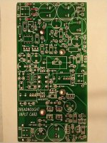
Dreadnought sans 4 diodes
Jumper as in the photo? Wish I was slower in building (usually pretty slow anyway) as they are already installed in the amp.
These four Front End card designs: Scourge, Bulwark, Marauder, and Dreadnought ... are older than you might think. They were designed in August and September of 2020, to meet the best-guess specifications and VFET amp requirement estimates, at that time.
And, it's not a big shock: things have changed. I've been in several discussions with Nelson Pass about future versions of the amp, and those amps aren't going to exactly match our guesses of ten months ago. Surprise!
In particular, the Front End cards don't need to be simultaneously compatible with (PositiveSupply, NegativeGround) amp cards, AND (NegativeSupply, PositiveGround) amp cards, AND (BipolarSupply plus Ground) amp cards.
So there's a bunch of complexity on those Front End cards, that has turned out to be unnecessary. It's no longer needed. And so I have decided to revise each of the four Front End cards to get rid of the unnecessary components and eliminate the unnecessary circuitry. I made this decision after consulting with Nelson (of course), and he supports the change. The new revisions are already posted to this thread and are attached to post #1. You can view them right now.
These edits are quite simple
- A small number of components have been removed from each board
- In some cases, the removed component is replaced by a short circuit (a copper track on the PCB)
- In other cases, the removed component is not replaced at all. It becomes an open circuit
- Zero new components have been added. Not a single one.
- No component values (e.g. resistance) have been changed
- A couple of rows have been removed from each Detailed Parts List. No new rows have been added.
- The Mouser One-Click Shopping Carts have been revised to match the new Detailed Parts Lists.
- If and when PCBs + kits of all parts become available in the diyAudio Store, they will (of course) use these versions. The latest versions.
For those brave souls who have already ordered PCBs and/or ordered parts and/or begun stuffing and soldering: you will have an easy time implementing these changes. Some parts you simply cut off the board with flush-cutters. Other parts you simply flip the board upside down and solder a bare wire to short the part's two leads to each other -- you can either let the part remain on the board (shorted out), or cut it off after shorting. Either way works just as well, it's your choice.
The good news is: the new revision boards actually sound better than the original versions (!!). Why? Because it turns out that the revised circuits are now fed from lower-impedance power supplies. That means better PSRR, and less MeanWell switchmode crud injected into the audio circuits. I'm delighted that simpler is also better, in these cases.
I've also updated the offsite (non-diyAudio) web links in post #1, so they now point to offsite safety copies of the latest revision.
Anyone who has already started building the previous board revisions, and who is doubtful or confused: send me a PM and I'll try to answer your questions. Be sure to include a picture of your bare PCB, as proof that you're a real builder and not a time waster.
The changes are:
- Scourge: remove 4 diodes and remove 3 resistors
- Bulwark: remove 4 diodes and remove 3 resistors
- Marauder: remove 4 diodes
- Dreadnought: remove 4 diodes
Jumper as in the photo? Wish I was slower in building (usually pretty slow anyway) as they are already installed in the amp.
Attachments
Anyone who has already started building the previous board revisions, and who is doubtful or confused: send me a PM and I'll try to answer your questions.
Glad to help.
I've had the dreadnought boards installed for several days of burn-in. Finally got a chance for extended listening and here is my first impression:
Dreadnought’s kung-fu is quite good. If Dreadnought was a martial artist I would say he most resembles Sammo Hung. The bass is more rounded, a bit more authoritative, but not soft or jiggly. The soundstage is more forward and larger giving individual instruments more separation and distinction. Tonally it is more neutral in the mids and highs versus the sweetness of the stock.
Other:
As quiet as stock front end.
The PCB is larger. If placing at the very back of the heatsink nearest the inputs, you will want to use 15mm standoffs as 10mm abutted the screws/nuts that hold the back plate.
Thanks to MJ, NP, 6L6. I look forward to trying other FE stages
Thank you for sharing your listening impressions! And congratulations on succeeding with your build; those are a couple of significantly complicated boards!! Good on ya.
The stock Front End card with two Toshiba JFETs, has an Edcor step-up transformer. Dreadnought has no transformer. Maybe the transformer (or lack thereof) will turn out to be the single biggest influence upon the sonic character of this amp (??) Of the eight front end cards that I am aware of personally, five have an Edcor transformer, and three do not.
With Edcor: Original NP Toshiba FE, Scourge, Bulwark, Relentless, FE#7
Without Edcor: Dreadnought, Marauder, FE#8
FE#6=Relentless has not been publicly released; it is a surface mount board. FE#7 is done and out for review. FE#8 is still on the drawing board.
Eureka insight from Marauder + Dreadnought JBOOST1 experimentation
Over on another thread, I saw that builders have begun to play around with the (Vout versus Vin) characteristics of the DC-to-DC converter on these boards. Its circuit is called JBOOST1 and appears on page 2 of both the Marauder schematics and the Dreadnought schematics.
I think this is a wonderful idea, and I predict it will be fun, exciting, surprising, and educational. By all means, give it a try! And please post your findings HERE so others can learn from your efforts as well.
If you've studied DC-to-DC converters, and/or the datasheets of ICs which form the heart of such converters, you've probably noticed that many of them contain a sub-circuit called UVLO -- Under Voltage Lock Out. This is a little sniffer circuit which monitors the incoming supply voltage (nominally +36V for Marauder and Dreadnought). If the incoming supply voltage is "too low", the converter shuts itself off, for self protection. However if you hunt for UVLO circuits on the JBOOST1 schematic, you won't find any. There is no under voltage lock out in JBOOST1. You can't hurt it by applying "too low" input voltage. You CAN make it work less and less well, by drastically lowering the input voltage, and you CAN make it stop working altogether, but neither of these are harmful to the circuitry. So go ahead and experiment / play around with lower input voltages, you won't damage anything.
Use your DVM to measure Vout and Vin, for several different choices of Vin (supplied by your adjustable power supply. Set its current limit to 35mA just for protection). Then plot these as a scatter diagram; an Excel Chart would be a handy vehicle for the diagram.
Study the plot and ask yourself: does that look like a straight line (a "linear function")? After all, JBOOST1 does contain some fairly nonlinear components, including regular BJTs, Darlington BJT, Schottky diodes, and Zener diodes. Maybe these nonlinearities somehow manifest themselves in the shape of the (Vout vs Vin) curve.
If your measured data does look like a straight line, Excel contains a feature to plot a linear regression Trendline and tell you the goodness-of-fit "R squared". If the data looks like a straight line, see whether you can come up with the equation of that straight like:
Vout = SLOPE * (Vin - DELTAV)
(Vout, Vin) are measured data; SLOPE and DELTAV are coefficients which you derive from your measurement data.
Thought Problem #1: Is there anything "intuitive" about the numerical value of SLOPE, from your own measured data? Does your SLOPE happen to be an integer multiple of 0.5, for example? If so, is that illuminating? Could SLOPE have been predicted from first principles, even before measuring real hardware?
Thought Problem #2: Is there anything "intuitive" about the numerical value of your DELTAV? Could DELTAV have been predicted beforehand?
On the other hand, maybe your data does not match up with a straight line. Maybe it's a curve. Excel offers a few other Trendlines that might fit your data better. Give em a try and have some fun.
If your (Vout vs Vin) data is not a straight line, then there are places where the slope (dVout/dVin) is greater, and placed where the slope (dVout/dVin) is smaller. If you want to, you can say that JBOOST1 "works better" in zones with larger (dVout/dVin) and JBOOST1 "works worse" in zones with smaller (dVout/dVin).
Thought Problem #3: is there anything "intuitive" about the positions of the zones where it "works better" and "works worse"? Is it obvious that JBOOST1 MUST "work better" at low Vin, and "work worse" at high Vin, for example?
Finally, if you have a digital scope with 2 or more channels, you can take a picture of JBOOST1 starting up. Connect Channel1 to the 36V supply, trigger on rising edge, trigger level +28V. Connect Channel2 to the JBOOST1 output node "POS_BOOSTED". Set the scope to capture a single sweep, and turn on the SMPS. Adjust vertical gain and horizontal speed as necessary. When you've got a nice trace of the entire event, snap a picture.
Now reason about your picture. WHY is the behavior that way? Does JBOOST1 wake up fast? Or is it slow? How fast/ how slow? Is the wave shape a linear ramp? An exponential? Something else? Are there surprises? And so on.
Oh, a quick warning: the OPA2134 used in the Polarity Invert section of these boards, is connected to the input power supply. Its maximum rated supply voltage is 36V. So don't apply more than 36V to your Marauder or your Dreadnought during experimentation. Lower is okay, higher is dangerous. I suppose you could pull the OPA2134 chip out of its socket (and also the OPA552 on Dreadnought), but that's still a little dangerous and a little sinful.
This discussion brings up an important point – the max supply voltage limit of the OPA2134. Those using the kit SMPS need only worry about their unit staying within its rated +/– 2% output voltage tolerance. But even with this tolerance, the Dreadnought card does not provide overvoltage protection for the OPA2134. The LM311 comparator has protection, but the OPA2134 does not.
The Marauder front end has overvoltage protection on its DC input, so both the LM311 and OPA2134 are safe on this card.
I may be one of the few FAB using an external capacitance multiplier PSU. With the standard front end, and the Edcor based front ends, this is not an issue. However, my PSU tends to run at a slightly higher voltage. I need to put it back on my bench and re-adjust it to maintain a safe voltage. I would advise any other builders using a linear PSU to do likewise.
- Home
- Amplifiers
- Pass Labs
- Scourge, Bulwark, Marauder, Dreadnought "front end" cards for DIY VFET amp