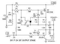
Are you referring to the P channel VFET circuit which was just released?
That is not a mu follower / SEPP - the mosfet is a constant current source.
I don't recall doing a mu follower Sony. I considered it, but the 2SJ28
likes a constant current source with an 8 ohm load, as does the 2SK82,
the next version up.
Ah, my error.
I reasoned falsely  that there was a slight modulation of the source because of the 'tap' of the output on the south side of the R1 resistor. But now I relook at it, indeed, only tapping on the north side or halfway would make it into a MU-stage like the ACA.
that there was a slight modulation of the source because of the 'tap' of the output on the south side of the R1 resistor. But now I relook at it, indeed, only tapping on the north side or halfway would make it into a MU-stage like the ACA.By the way, does a source-follower with a SIT specifically match best with a CCS feed - in the sense that this will also be the case with the 2SK180/2SK182 in this same topology?
albert
Depends on load impedance and what harmonic profile and Ids and Vds.
Mu follower multiplies load impedance.
- Typical desired impedance for 2sk82 or 2sj28 is about 8 Ohms.
- Typical impedance for 2sk182es is more like 16 Ohms
Does that imply that a 2SK182 'likes,' or matches good with, a transformer 32/8 ohm?
And that with a mu stage 8 ohms looks like maybe 16 ohms (i.e. easier to drive the lower ohmic valued load)?
Too many variables . . . both I and V, and R, for any conclusions on my side. LTSpice easily gives me output, but that is quite different from the real field experiments.
Thanks.
I hope there will be a bare Mu-follower board in the shop to work with.
In case the 2SK180/182 is used as source follower, then the load would be a CCS like the 2SJ28 and the expected 2SK82 versions, I reckon, the output impedance being lower.
I hope there will be a bare Mu-follower board in the shop to work with.
In case the 2SK180/182 is used as source follower, then the load would be a CCS like the 2SJ28 and the expected 2SK82 versions, I reckon, the output impedance being lower.
[My bricolage is error-prone and I dare not pass my builds to others.]
Unmatched 2SK82
Considering chances of me getting the kit from lottery are slim to none, I managed to get two 2SK82 in preparation when VFET-less kits are available for sale.
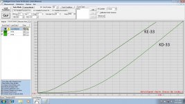
Both 2SK82 have different production codes (KD-33 and KE-33) and when I tested on LockyZ curve tracer, the result is clearly unmatched V-Fets (curve is attached).
The Vgs difference is approximately 2 volts, but they both showing pretty close linearity.
Looking at the schematic and description in the documentation, I think the Vgs difference can be compensated by adjusting P1.
Would there be any other issues for building this VFET with these unmatched K82s?
Considering chances of me getting the kit from lottery are slim to none, I managed to get two 2SK82 in preparation when VFET-less kits are available for sale.
Both 2SK82 have different production codes (KD-33 and KE-33) and when I tested on LockyZ curve tracer, the result is clearly unmatched V-Fets (curve is attached).
The Vgs difference is approximately 2 volts, but they both showing pretty close linearity.
Looking at the schematic and description in the documentation, I think the Vgs difference can be compensated by adjusting P1.
Would there be any other issues for building this VFET with these unmatched K82s?
Attachments
There is a future F5. Not turbo, but special...

Toshiba power mosfets are readily available for these special F5s!
Looking at the schematic and description in the documentation, I think the Vgs difference can be compensated by adjusting P1.
I think so too. If you run out of adjustment range on P1, you might be forced to replace R8 (27K) with a resistor half as big, perhaps 12K. I'd suggest soldering R8 in such a way as to make it very easy and low-risk to unsolder & replace it. Leave R8's leads exactly perpendicular to the PCB, etc.
_
Attachments
Toshiba power mosfets are readily available for these special F5s!
You mean these Toshiba To-3 ones too like I have in the Classic version?
That would be fun. Rusty but oh so effective.


Last edited:
It would be nice to know what my diets missing out on.
Interesting choice of words.
I borrowed the DIY Sony VFET from SRMcGee (Thank you Scott!) and just finished listening to it a few minutes ago.
Been swapping it out in and out for 5 days.
One special attribute of the amp is its ability to let your hear in between the notes. In other words- What you're missing out on.
It serves up a more complete version of the music I have been listening to for months now.
Only compared against simulated J2 with unbalanced inputs. Notice I didn't say J2 or J2 clone.
Last edited:
Those are Hitachi.

Indeed the Hitachi laterals; very nice neg tempco and easy to drive.
Which Toshiba (laterals??) are recommended then for an F5? > in flat case To-247
Long obsolete, the 2SK1530/2SJ201 don’t seem to have a reliable source. I have had better luck finding the big SITs than these old lateral Mosfets.
What I do have is a collection of the old lateral Mosfets used in the Hafler amplifiers. Matched even, as I had a hobby of buying the old amps for their parts.
What I do have is a collection of the old lateral Mosfets used in the Hafler amplifiers. Matched even, as I had a hobby of buying the old amps for their parts.
- Home
- Amplifiers
- Pass Labs
- DIY Sony VFET pt 1