In the not too distant future there should be an EQ circuit designed by Nelson Pass that will eliminate shout on FR drivers. It's the best thing since sliced bread! I'm using it on my SEAS FRs and it is nothing less than fantastic!Yep. They're the garage test speakers. They're still shouty but also have that distinctive resonant horn effect in the midbass.
Nice job on your VFET kit!!!
Yeah that's a project I've had in the back of my mind for a while, looks like some fine hand skills needed to lay out & paint all those little rectangles")
The much easier pre-EnABL mods are what really do a lot to tame the top.
dave
I have the BK108 Eckhorn & FE108sigma horns and I've matched it with my VFET (2SK82) but, it is shouty - and the vendor sold me a step correction (not really baffle step correction); in his horn the low mid dissappears, so a step just abocve that "should straighten it all out". It does not. The sound is not natural. [I bought the complete horns in Covid lockdown mode, no listening]
I installed the Fostex FE10 parallel impedance corrector. That is better.
But still not the most top experience I had with my old old FE103Sigma in TQWT. Far far from that.
I installed the Fostex FE10 parallel impedance corrector. That is better.
But still not the most top experience I had with my old old FE103Sigma in TQWT. Far far from that.
- So Dave, if there is a suggestion . . . on how to equalize this ??

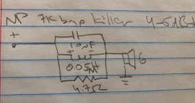
There's a 7k tank circuit that NP designed. I don't remember where I saw it, maybe in the current source docs? Was thinking of trying it but haven't yet.I have the BK108 Eckhorn & FE108sigma horns and I've matched it with my VFET (2SK82) but, it is shouty - and the vendor sold me a step correction (not really baffle step correction); in his horn the low mid dissappears, so a step just abocve that "should straighten it all out". It does not. The sound is not natural. [I bought the complete horns in Covid lockdown mode, no listening]
I installed the Fostex FE10 parallel impedance corrector. That is better.
But still not the most top experience I had with my old old FE103Sigma in TQWT. Far far from that.
- So Dave, if there is a suggestion . . . on how to equalize this ??
Attachments
So Dave, if there is a suggestion . . . on how to equalize this ??
BK108? FE108∑?
I am not familiar with the first, but i have a good ideam likely produces little real bass. The FE108∑ is something i have not seem but the pre-EnaBL mods, modpodge/puzzlekoat, and ZIG 2-way glue. Has help with the resonances in all the FExxx & FFxx5wk drivers (the last ned a bit different detail on the metal dustcaps.
I tend to avoid filters and attack the problem at the source.
dave
It is the FE108∑. Thanks Ranshdow I followed up the filter now - though slightly different: 0,39mH//5,5ohm//10 uF, and the a high frequency smoothener: parallel 22 ohm and 22uF+5,1 ohm - direct on the terminals, to take away a slight harshness. It is great now!
Dave yes you are right, the ‘new design filosophy’ at Fostex is a 3-point suspension of the dome, really bad. It will swing independent of the cone. So as such it is a sort of coax, with all the problems. I thought of putting glue in the hole! Probably what you suggest as the 2-way/2 component glue. But I dare not.
I loved the old FE103 Sigma. My new sound is superb with the V FET.
ps I also have 5,6 mH//5,1 ohm, and 10uF to be added. I can compare.
back to the V FET: it is great, makes me cry of joy.
Hi
Following recommendation from Mark J, i am posting a question about the design philosophy of the DIY VFET & Ship of Theseus regarding power supply. Originally posted here https://www.diyaudio.com/community/...ngeable-amplifier-modules.383745/post-7239103
"Hi
From the schematics of the Ship of Theseus, i kind of understand that only +36volts is used.
With linear power supply and amp like F5, M2x, i understood why we used +24volts and -24volts.
1) am i correct understanding that Ship of Theseus use only +36v?
2) if yes above, can somebody explain the difference between Ship of Theseus and others like First Watts amp?"
= is it because the DIY VFET is Single Ended (and i would assume Ship of Theseus also is) ?
Thanks in advance if somebody can answer.
Ship of Theseus uses a single ended +36V power supply because its goal is to be 100% electrically compatible with the Sony VFET kits sold from the diyAudio Store (by lottery) in 2021. You want to know why the DIY Sony VFET amp used a single ended +36V supply.
You also request that somebody explain to you the difference between amps that use single ended supplies (like DIY Sony VFET), and amps that use "bipolar" power supplies (like First Watt M2).
Although plenty of members might be perfectly willing to make a guess about the first question, only NP is able to offer an authoritative and guaranteed-correct answer.
Last edited:
Educated guess would be fine by me. And if later NP corrects it, i guess we would have learned something interesting. Take care!Ship of Theseus uses a single ended +36V power supply because its goal is to be 100% electrically compatible with the Sony VFET kits sold from the diyAudio Store (by lottery) in 2021. You want to know why the DIY Sony VFET amp used a single ended +36V supply.
You also request that somebody explain to you the difference between amps that use single ended supplies (like DIY Sony VFET), and amps that use "bipolar" power supplies (like First Watt M2).
Although plenty of members might be perfectly willing to make a guess about the first question, only NP is able to offer an authoritative and guaranteed-correct answer.
From the original article by N. Pass published here before the first lottery:
The 2SJ28 is operated as a follower (CD), with the Drain at ground and biased by a constant current source at 1.6 amps. The power comes from an external switching supply at +36 volts. The loudspeaker is driven by the Source pin of the VFET through a large capacitor. The Gate of the VFET is set at a DC voltage which puts the Source pin at +20 Volts DC, and is driven by AC signal from a separate circuit, seen here as the X5 block. In the base front end version, a Jfet buffer drives an Edcor transformer to create the X5 voltage gain. All the circuits are Class A, Common Drain, and without feedback loops. You may note that we invert the polarity of the input and also the output polarity. This is done so that we can get the desired second harmonic characteristic of the amplifier and also preserve the absolute phase of the signal.
You may wonder why the Drain of the VFET is attached to ground. The reason is that the Drain impedance of the VFET is quite low compared to regular transistors, and any noise that appears on the Drain is going to make it to the output signal. Since Ground is the quietest spot in the circuit, it is logical to attach the Drain there. In the N channel version this is still true, although the supply voltage for the current source becomes negative instead of positive.
Only Papa can reply, but for the night a very personal and somewhat humoristic answer from mine to "why the DIY Sony VFET amp used a single ended +36V supply"
Because... It can.
It does not require a bipolar supply, is hence simplier and moreover that enables the use of a SMPS (as these come easier in that power supply format than bipolar). Properly filtered IMHO the SMPS has its virtues for Class A, but indeed also detractors: let's just say that Papa made it work. Oh, and as an industrial, I can quite see that selling kits around the world without having to bother about the PS (= black box from reputable mass series) and various norms, or some legal aspects due to DIYer diving into a big conventional PS with their head first with a watering mouth, is quite a plus.
Have good night folks
IMO, the single ended VFET version using single rail SMPS fits perfect bill for a real DIY friendly approach (NP's brainchild).
I had just completed and had the chance to hear the first channel of SE P-channel VFET that I luckily won from the lottery (I'll post pics once both channel complete). Beside heat sink provisioning, I can say this had been the easiest DIY I've ever built.
Thank you so much NP, to Jason and to all involved in the lottery.
Thanks for the different pointers / text highlights.
On the power supply choice, i completely agree it makes the DIY much easier / safe, if one begins/has to learn. (i was a bit scared when assemblying 220V to 18V-AC and 24V-DC linear power supply for M2x. Got a verification from a workmate working with electricity, helps networking / making contacts...)
On the power supply choice, i completely agree it makes the DIY much easier / safe, if one begins/has to learn. (i was a bit scared when assemblying 220V to 18V-AC and 24V-DC linear power supply for M2x. Got a verification from a workmate working with electricity, helps networking / making contacts...)
I know SMPS tend to have higher efficiency and place any switching noise outside the audible spectrum (instead of 60Hz or it's lower order harmonics), but come at an increased cost due to complexity and parts count (for a serious, properly designed SMPS). Tho, big iron isn't cheap either.Properly filtered IMHO the SMPS has its virtues for Class A, but indeed also detractors
I'm curious what else folks would say on the matter of pros vs cons of a proper SMPS in class A.
Thanks for the answer!Single ended amp, single ended supply?
Mostly it made it easy with existing switching supplies and no worries about DC offset.
There is another thread with lots of information on this amp, including use of SMPS and linear power supplies..
Thread 'DIY Sony VFET Builders thread'
https://www.diyaudio.com/community/threads/diy-sony-vfet-builders-thread.370689/
Thread 'DIY Sony VFET Builders thread'
https://www.diyaudio.com/community/threads/diy-sony-vfet-builders-thread.370689/
- Home
- Amplifiers
- Pass Labs
- DIY Sony VFET pt 1