
@baeijsman: It is a SlimDevices/Logitech Transporter.
https://www.stereophile.com/mediaservers/207slim/index.html
I started with a squeezebox classic long ago and still love them (I use the old classic in my shed). I then upgraded to a Transporter in my main system and it is really nice, especially using the balanced outputs. [I built a single ended Fetaudio FDA-1 about 11 years ago (PCM1794A), expecting an improvement, but the Transporter's internal dac sounds better.]
The problem with big companies like Logitech is that they see a market but can't be bothered (or don't have the expertise) to develop something in house. So, they just buy whatever company has a good product (e.g. SlimDevices), market the hell out of it to sell as many as possible and then discard it to do something else, hoping the owners will buy into their new product range (probably designed by their latest acquisition).
Luckily the squeezebox server software is open source and still actively maintained. A third party plugin even offers on the fly dsd-pcm conversion (the Transporter is limited to 24 bit 96kHz pcm) and there are all kinds of third party plugins for streaming services and many other features. I am old fashioned and just use mine with the music stored on my Linux server
You can also use a simple raspberry pi as a source (e.g. piCorePlayer / Squeezelite), so even if you have no squeezebox units, it is still a good option. And there are apps to use your smartphone as the remote.
The Magnepan MG3As have mid/hi and bass inputs. These are connected to an external (passive) crossover, to which you would connect your poweramp. So while it does have separate connections for mid/hi and bass, the bass panel is conected directly to the bass inputs (and you don't want to feed the full range signal to the bass panels). Which means I can't duplicate your setup, but using an F4 to add a bit more power to the VFET for mid/hi is still a good option to try.VFET single ended plus F4 between VFET and woofer binding posts on my speakers sounded great 👍. Different speakers mind you. This added authority while preserving the VFET sweetness on top.
An old, but very very good, electronic crossover was the Levinson LNC-2 (1980s vintage I think). They had potted electornic modules with fixed frequencies (you had to order them with the correct frequencies installed), so trying to find a second hand one with the correct frequencies is a waste of time. I have heard the MG3As using the LNC-2 and knew what the MG3As were capable of. Much, much better sounding than with the standard external crossovers.
I was on a budget, bought my MG3As second hand from a dealer and bought a Behringer crossover to biamp, but it does not come anywhere near the LNC-2. After reading a speaker review (NHT Evolution T6) 18 years ago, I decided to try to run the MG3As mid/hi "commando" and have never looked back. The improvement was much larger than I expected! I am not really sure if using the LNC-2 would be an improvement (too much time between hearing them and unknown what the other parts of the chain were). I never tried the XVR-1. I would have loved to try one, but never saw one come on the market second hand, let alone for a reasonable price.
See the review and follow up in stereophile for an explanation of driving the speaker commando:
https://www.stereophile.com/content/nht-evolution-t6-loudspeaker-system-postscript-may-2005
It will be interesting to see what the sound is like when I put an F4 between the VFET and the MG3As mid/hi inputs. At 10W into 8Ohms, the VFET should be able to deliver 9V, which should give me 20W into 4Ohm, so 4 times as much as I am currently getting (and at lower distortion).
Not sure what load to put on the VFET. I assume something like an 8Ohm or 16Ohm resistor? You had your mid/hi as load on the VFET, so would not have needed to add an extra load.
But first I need to enjoy the current combo for a while
PS I think Magnepan made a mistake when they dropped the option to biamp from their 3 series, which is why I opted to ave my MG3As rebuilt. To me, in my system, they sound much better than the newer 3.7s.
Very impressive.
My VFet build (2SJ28 version that is) was measured last week having a max power (at x%) of about 6Watts, at 750mV RMS in.
No surprise the VFet works to power the Magnepans. I once demo'ed the Le Monstre 8W into the Magnepans with the two side boards, the folding one (don't know the model) Not extremely loud but excellent stage.
Another Albert from Holland

@triode_al Originally from NL but moved Australia sometime after I joined diyaudio
Just a picture of a screenshot of my V-FET 2SJ28, showing high frequency noise from the SMPS, even though I have the 'standard' minichoke and caps for smoothing:

By the way I see nada none keine no harmonics. Just buried in the noise as far as I can see . . more to follow later
(I have an exeptional driver stage with PCC88 and a choke on the same power rail)
By the way I see nada none keine no harmonics. Just buried in the noise as far as I can see . . more to follow later
(I have an exeptional driver stage with PCC88 and a choke on the same power rail)
It was Audio Precision. Yes you'r right. Not fiull driven. Here some report pages. V-FET 2SJ28
The VFet amplifies +10,3 dB. And at 2,8Vrms it is 0,16%; peak level
Distortion Product Ratio in dB, - Generator Level Ch1: -0,000 dBrG (@860,2 mVrms)
Sweep volume:

THD Ratio against volume

Distortion Product ratio (H2) is pretty constant

and which power at 1%?:
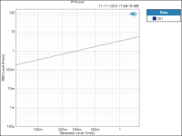
RMS Level
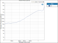
THD+N Level
THD+N Ratio
In the following I can't really make sense. I see that the mauve line H4 is higher than the others?? But what is then the line at -30 dB? It is not the generator nor the output because those are flat.

The VFet amplifies +10,3 dB. And at 2,8Vrms it is 0,16%; peak level
Distortion Product Ratio in dB, - Generator Level Ch1: -0,000 dBrG (@860,2 mVrms)
| Channel | F | H2 | H3 | H4 | H5 | H6 | H7 | H8 | H9 | H10 |
| 1,000k | 2,000k | 3,000k | 4,000k | 5,000k | 6,000k | 7,000k | 8,000k | 9,000k | 10,00k | |
| Ch1 | -0,00 | -67,38 | -59,18 | -88,36 | -95,27 | -102,76 | -108,42 | -120,18 | -113,27 | -110,63 |
Sweep volume:
THD Ratio against volume
Distortion Product ratio (H2) is pretty constant
and which power at 1%?:
RMS Level
| Ch1 | 5,317 | W |
| Ch1 | 65,17 m | Vrms |
| Ch1 | 0,999787 | % |
In the following I can't really make sense. I see that the mauve line H4 is higher than the others?? But what is then the line at -30 dB? It is not the generator nor the output because those are flat.
Attachments
I don't have an AP nor have I ever used one so I can't help you with its use or understanding of the -30dB plot.
I noticed in the first chart that H2 was lower than H3 at 1W. That is not usual for this amplifier.
Also the graph of THD Level vs Generator Level showed decreasing THD as the power increased, until the THD bottomed out and then the THD started increasing. That is also not usual for this amplifier.
The graphs would be easier to understand if the horizontal axis was set to output, whether Vrms or Watt, instead of Generator Level (Vrms). Is the Generator Level (Vrms) representative of the DUT output?
Is the Generator Level (Vrms) representative of the DUT output?
The generator is 10.3 dB lower than the output and very flat within 0.1 dB; in the sense that the amplification is +10 dB and the reference is valid.
In my quest for relief from "audiophile nervosa", I am curious if there are any owners of the F2J (using full-range drivers, especially Lowther-ish ones) who have also tried the VFET follower. I understand it's like "comparing apples to oranges", given the significant influence of the frontend, but I'm hoping someone can provide insights on the subject
BTW, in simulations, I observe that the current output is much more precise in the F2J, especially for non-resistive loads. In the VFET, being a follower, it takes feedback from the load and its own output impedance, also allowing for current decay with inductive loads.
BTW, in simulations, I observe that the current output is much more precise in the F2J, especially for non-resistive loads. In the VFET, being a follower, it takes feedback from the load and its own output impedance, also allowing for current decay with inductive loads.
I'm looking to build the Sony SE P-channel VFET somewhere down the road. I tried the lottery back in 2021, but lost out. I recently snagged one of the last boards in the store and now I need to get a pair of very expensive VFETs. Looking at curve traces assuming there are two good matched pairs of 2sj28 to choose from, is the pair with higher gain (mu) a "better" choice, or is there another parameter that takes precident? I noticed the lottery VFETs were matched based on a Vgs within 0.1V of one another at 1.6A 20V, however, with curve trace matching, there are plenty other available parameters to consider as well.
@KevinHeem
Well, building appears to be the only practical option since existing lottery amps are pretty quick to get snatched up anytime they go on sale. I'm ok either building or buying.
Well, building appears to be the only practical option since existing lottery amps are pretty quick to get snatched up anytime they go on sale. I'm ok either building or buying.
@jugi63
Thank you for bringing it up!
I'm not sure how, but I lucked out and was able to get a chassis and pair of VFETs a couple weeks back. I've got a few projects in the list before the build, and still some parts to acquire, but it looks like I'll be able to build a Sony P-channel VFET! So much fun!
Thank you for bringing it up!
I'm not sure how, but I lucked out and was able to get a chassis and pair of VFETs a couple weeks back. I've got a few projects in the list before the build, and still some parts to acquire, but it looks like I'll be able to build a Sony P-channel VFET! So much fun!
- Home
- Amplifiers
- Pass Labs
- DIY Sony VFET pt 1