check trimpots
You mean to turn them to rebias? Or make sure they are intact?
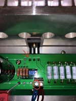
My measurement to power ground is the same...currently 3.17 V DC.
Power ground reference circled in pic.
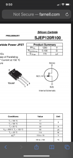
I was worried about testing incorrectly...that’s why I looked up the data sheet at Farnell.
Power ground reference circled in pic.
I was worried about testing incorrectly...that’s why I looked up the data sheet at Farnell.
Attachments
I’m always so paranoid about having to solder these expensive “unobtainium” parts.
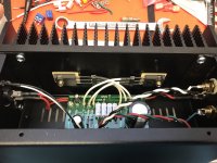
I wanted to try a pair of r100 in the ACAs I built previously and went as far as making sockets with pigtails to run to the circuit board to avoid overheating and allow reuse of them in another amp if I wanted.
In my F2Js there wasn’t really room for the pigtail/socket, so I first quickly tagged on extensions made of cutoff tinned legs from previously mounted 2 watt resistors. I’m always using flux paste to make sure things flow as quickly as possible.
Afterwards, I insulated the extensions with heat shrink tubing.
Being able to position and mount them to the heatsink before mounting to the circuit board gave me a bit more peace of mind.
Attachments
Sigh! Seems the Jfets are ok then! From all of your advice?I also suspect that the potentiometers show mal function, just try to change the voltage of the drain to ground with the poti.
In my F2J one SJEP left me, but this was due to overheating during soldering (I had to repeat the soldering due to a bad conection)
That’s my biggest concern , what caused that shift? Is it expected from a perfectly biased to unbiased. Potti are that unstable?
Just afraid to turn the pots if that is not the case.
I have an 8ohm ,100watt dummy load connected at speaker out.
So I should have about half the voltage at C2 positive pin wrf to ground for biasing ?
I tried to turn the pots and no change in voltage readings. Is it that common for trim pots to fail that too both side.
Ps: I only tried one side
https://www.diyaudio.com/forums/att...2-f2j-trouble-shooting-help-f2j-schematic-jpg
Last edited:
what you can always do is - check resistors and trimpots with ohmmeter
if in doubt, lift one end of resistor and check it that way
same applies to trimpot
no use of just writing here, and waiting miraaaaacle to happen
something is Dodo , now is up to you to do the job - I did wrote what to do and in what order
if in doubt, lift one end of resistor and check it that way
same applies to trimpot
no use of just writing here, and waiting miraaaaacle to happen
something is Dodo , now is up to you to do the job - I did wrote what to do and in what order
Zen mod, it is a board with very few components and I never heard a pot failing on both sides at the same time.
Before taking the board out which will be a hassle ,I am trying to see it’s worth the effort.
As much I wants to believe both trim pot failed but it is almost like I even winning a lottery.
Or rather make a new Board !!
Before taking the board out which will be a hassle ,I am trying to see it’s worth the effort.
As much I wants to believe both trim pot failed but it is almost like I even winning a lottery.
Or rather make a new Board !!

Chromenuts, can you please let me know the voltage between
EB
BC
EC voltages of ZTX 550
I am getting
EC 18v
BC 18V
EB zero Volt
Also in case a deleterious voltage comes through input say 2 V Dc , will it damage ZTX 550 or IRFP240 ?
My audio input device is also not working.
EB
BC
EC voltages of ZTX 550
I am getting
EC 18v
BC 18V
EB zero Volt
Also in case a deleterious voltage comes through input say 2 V Dc , will it damage ZTX 550 or IRFP240 ?
My audio input device is also not working.
Last edited:
Hi kinku
Wasn’t sure what you meant... so I looked up the ztx550 datasheet.
You want voltage measurements between:
Emmiter/Base
Base/Collector
Emitter/Collector
I have no idea about your question regarding an input voltage spike and its effect on the 550.
I’m out picking up dinner for the family right now. I’ll try and take a look later.
Yup you got it right Chromenut , it’s emitter , base collector.
No worries take your time. Before dismantling the board I am trying one last thing.
The input device was for everyone involved.
I think my streamer is broke and on his way down it possibly damaged my amp too. Streamer out put has a DC voltage of 0.6V.
It is not working with other devices too.
No worries take your time. Before dismantling the board I am trying one last thing.
The input device was for everyone involved.
I think my streamer is broke and on his way down it possibly damaged my amp too. Streamer out put has a DC voltage of 0.6V.
It is not working with other devices too.
Last edited:
Hi kinku
So I took measurements of the ztx550 @ Q3 in the circuit using the datasheet from Mouser as a pinout guide making sure to note how the beveled edges indicate its orientation and pin locations.
I didn’t want to risk shorting the pins as it was a little tricky hooking onto them with my probes.
I measured by clipping onto the 550s legs a pair at a time and then flipping the power on and waiting 30 seconds or so for the voltage to stabilize.
My measurements were:
EB 4.65 V DC
BC .60 V DC
EC 5.28 V DC
I hope this might help you in your search for the problem.
there is no significant current through output vertical , if output node is practically at rail potential, so no use of measuring voltages across R16/17
fist thing is to check voltage at Q1 gate , that'll confirm fucntionality of P1
if there is 1V5 or so, it's time for pulling both Qs out and check - first with diode test, then with anything else - either with modern measure-it-all Gizmo or in proper mosfet check jig
........
")
- Status
- This old topic is closed. If you want to reopen this topic, contact a moderator using the "Report Post" button.
- Home
- Amplifiers
- Pass Labs
- F2/ F2J trouble shooting help