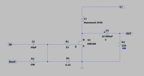
25W Single Ended Hammond 193V Choke Loaded 2SK180 L'Amp
I'm a great fan of VFETs and SITs. I've built the Papa Pass diyAudio Sony VFET amp, Michael Rothacher Sony 2SK28 Hammond 193V choke loaded L'Amp and Luminaria (2SK82) preamp, Zen Mod SissySit with THF-51S, and Pappa Pass BAF2015 amp with THF-51S. Prior to these amps, I had tubes for many years - single ended parafeed 45 amps and filament biased 26 preamp. But I don't miss those tubes. It's VFETs and SITs all the way now, thanks to Papa Pass, Michael Rothacher, and Zen Mod.
So last March when I was looking for another project,Tokin 2SK180s were readily available on ebay. Since I didn't have any amps with them I decided to buy a couple and give them a try.
I decided to use the Hammond chokes from my 2SK28 L'Amp for this project and redo the 2SK128 L'Amp in the future with a mu follower current load. The amp was built into one chassis and it was very heavy - I could barely lift it. So it went through a weight reduction, and its 193V chokes will now be transplanted to bring new life to a pair of higher powered 2SK180 monoblocks based on Michael Rothacher's choke loaded L'Amp design. I really do like the single ended sound.
Since I couldn't find much information on the world wide web on operating points for higher powered choked loaded single ended 2SK180 amps, I had to figure something out. The other factor was that Tokin SITs have a large variance in their characteristics so even computer similations would not reliably predict good operating points. Despite that I did do some LTSpice simulations for the fun of it.
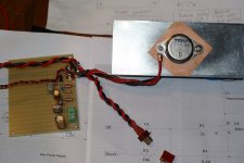
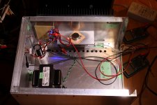
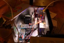
Before I could do live tests to figure out the operating point that I would use, I built some chassis to mount the Tokins and keep them cool. With all my previous projects, I had purchased ready made chassis. However there was a lack of ready made monoblock chassis with a single large heatsink, so I decided to purchase some aluminum plate and angle and build my own. I don't have a work shop or drill press but I made do with hand held tools, working in my kitchen, and now I have two reasonably presentable monoblock chassis.
All circuits are point to point wired on perf board. The actual signal amplification circuit is very simple, with minimal parts. The majority of the parts are in the bias supply and in the yet to be constructed V+ supply.
To be continued.
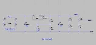
Edit: Power Supply
Edit: 2021-04-04 Added Information - Amplifier changed from Common Source to Common Drain (Follower): Common Drain (Follower)
Edit: V-Power Supply Version with PCB added:
- Start of V- Supply Version Posts
Edit: V- Power Supply Version with PCB, with Independent Bias Voltage Supply to Suit SMPS V- Supply
- Independent Bias Voltage Supply Version
Original Common Source Amplifier Below:
I'm a great fan of VFETs and SITs. I've built the Papa Pass diyAudio Sony VFET amp, Michael Rothacher Sony 2SK28 Hammond 193V choke loaded L'Amp and Luminaria (2SK82) preamp, Zen Mod SissySit with THF-51S, and Pappa Pass BAF2015 amp with THF-51S. Prior to these amps, I had tubes for many years - single ended parafeed 45 amps and filament biased 26 preamp. But I don't miss those tubes. It's VFETs and SITs all the way now, thanks to Papa Pass, Michael Rothacher, and Zen Mod.
So last March when I was looking for another project,Tokin 2SK180s were readily available on ebay. Since I didn't have any amps with them I decided to buy a couple and give them a try.
I decided to use the Hammond chokes from my 2SK28 L'Amp for this project and redo the 2SK128 L'Amp in the future with a mu follower current load. The amp was built into one chassis and it was very heavy - I could barely lift it. So it went through a weight reduction, and its 193V chokes will now be transplanted to bring new life to a pair of higher powered 2SK180 monoblocks based on Michael Rothacher's choke loaded L'Amp design. I really do like the single ended sound.
Since I couldn't find much information on the world wide web on operating points for higher powered choked loaded single ended 2SK180 amps, I had to figure something out. The other factor was that Tokin SITs have a large variance in their characteristics so even computer similations would not reliably predict good operating points. Despite that I did do some LTSpice simulations for the fun of it.
Before I could do live tests to figure out the operating point that I would use, I built some chassis to mount the Tokins and keep them cool. With all my previous projects, I had purchased ready made chassis. However there was a lack of ready made monoblock chassis with a single large heatsink, so I decided to purchase some aluminum plate and angle and build my own. I don't have a work shop or drill press but I made do with hand held tools, working in my kitchen, and now I have two reasonably presentable monoblock chassis.
All circuits are point to point wired on perf board. The actual signal amplification circuit is very simple, with minimal parts. The majority of the parts are in the bias supply and in the yet to be constructed V+ supply.
To be continued.
Edit: Power Supply
Edit: 2021-04-04 Added Information - Amplifier changed from Common Source to Common Drain (Follower): Common Drain (Follower)
Edit: V-Power Supply Version with PCB added:
- Start of V- Supply Version Posts
Edit: V- Power Supply Version with PCB, with Independent Bias Voltage Supply to Suit SMPS V- Supply
- Independent Bias Voltage Supply Version
Original Common Source Amplifier Below:
Attachments
Last edited:
Testing
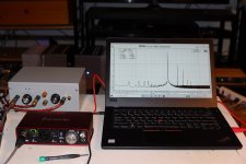
After putting together the bias supply and amplifier circuit, I powered it up with a lab supply, and did some FFT runs at various operating points.
For those of you who are not familiar with how easy it is to do distortion measurements:
Howto - Distortion Measurements with REW
My equipment:
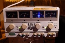
-Instek PC-3030 linear power supply, well used, that I recently purchased on ebay, for V+
-old 19V computer power supply for bias V-
-Focusrite Scarlett 2i2 Gen 2
-REW software
-diy voltage divider/attenuator https://www.akitika.com/documents/BuildingTheAttenuatorRev4.pdf
-Victor 1kHz oscillator (diyAudio member vicnic)
-8 Ohm amplifier load (2-4 Ohm resistors on heatsink)
The 2SK180 is a 300W device. I tried to keep the maximum dissipation to about 90W to hopefully allow the devices have a long life.
The operating points that I investigated:
V+ (V) Vds (V) Iq (A)
37.5 34.7 2.8
37.5 35.0 2.5
40.0 37.7 2.3
40.0 37.9 2.1
37.5 35.5 2.0
42.5 40.2 2.3
31.25 28.25 3.0
35.0 32.3 2.7
The V+ were chosen based on available Antek tranformer voltages, assuming a final rectified and filtered supply voltage equal to 1.25 x (transformer secondary VAC).
My goal was H2 dominant at lower power output, less than 1% THD at 1W (preferably much less than 1%), 5% THD maximum at 25W.
When I was researching the 2SK180 for purchase, I had read that "C" and "D" graded devices were most likely to have tightly grouped Vgs and curves. So when I purchased my untested "D" grades, I asked the seller for two devices with serial numbers that were close together. I ended up with serial numbers 130103 and 130110.
I built and tested the right channel first. V+=37.5V Vds=35.0v Iq=2.5A had the best results. I then built the left channel and tested it. The results were similar to the right channel, although not exactly the same. At the chosen operating point the left channel serial #130103 Vgs=-3.51V and the right channel serial #130110 Vgs=-3.23V. The FFT results for the right channel are shown below.
So with the operating point decided, two Antek AS-3430 (30VAC 300VA) tranformers have been ordered. I have been waiting for nearly two weeks now. USPS is slow. Power supply parts ordered from Mouser and were received two days later, shipped by UPS.
I also listened for three days with the right channel in my system, with the BAF2015 THF-51S in the left channel. I don't think I noticed much difference if any with the 2SK180 channel in place. That is a good thing. It may have even sounded a bit better. However I will not be able to listen to both channels together until I have the power supplies built. But I think this will be a very good or great sounding amplifier.
To be continued.
After putting together the bias supply and amplifier circuit, I powered it up with a lab supply, and did some FFT runs at various operating points.
For those of you who are not familiar with how easy it is to do distortion measurements:
Howto - Distortion Measurements with REW
My equipment:
-Instek PC-3030 linear power supply, well used, that I recently purchased on ebay, for V+
-old 19V computer power supply for bias V-
-Focusrite Scarlett 2i2 Gen 2
-REW software
-diy voltage divider/attenuator https://www.akitika.com/documents/BuildingTheAttenuatorRev4.pdf
-Victor 1kHz oscillator (diyAudio member vicnic)
-8 Ohm amplifier load (2-4 Ohm resistors on heatsink)
The 2SK180 is a 300W device. I tried to keep the maximum dissipation to about 90W to hopefully allow the devices have a long life.
The operating points that I investigated:
V+ (V) Vds (V) Iq (A)
37.5 34.7 2.8
37.5 35.0 2.5
40.0 37.7 2.3
40.0 37.9 2.1
37.5 35.5 2.0
42.5 40.2 2.3
31.25 28.25 3.0
35.0 32.3 2.7
The V+ were chosen based on available Antek tranformer voltages, assuming a final rectified and filtered supply voltage equal to 1.25 x (transformer secondary VAC).
My goal was H2 dominant at lower power output, less than 1% THD at 1W (preferably much less than 1%), 5% THD maximum at 25W.
When I was researching the 2SK180 for purchase, I had read that "C" and "D" graded devices were most likely to have tightly grouped Vgs and curves. So when I purchased my untested "D" grades, I asked the seller for two devices with serial numbers that were close together. I ended up with serial numbers 130103 and 130110.
I built and tested the right channel first. V+=37.5V Vds=35.0v Iq=2.5A had the best results. I then built the left channel and tested it. The results were similar to the right channel, although not exactly the same. At the chosen operating point the left channel serial #130103 Vgs=-3.51V and the right channel serial #130110 Vgs=-3.23V. The FFT results for the right channel are shown below.
So with the operating point decided, two Antek AS-3430 (30VAC 300VA) tranformers have been ordered. I have been waiting for nearly two weeks now. USPS is slow. Power supply parts ordered from Mouser and were received two days later, shipped by UPS.
I also listened for three days with the right channel in my system, with the BAF2015 THF-51S in the left channel. I don't think I noticed much difference if any with the 2SK180 channel in place. That is a good thing. It may have even sounded a bit better. However I will not be able to listen to both channels together until I have the power supplies built. But I think this will be a very good or great sounding amplifier.
To be continued.
Attachments
Right channel FFT results:
Attachments
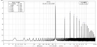
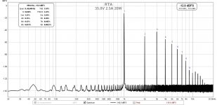
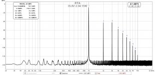
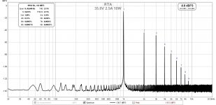
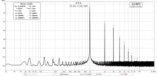
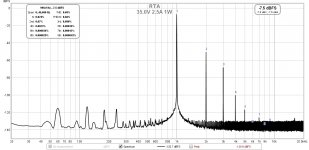
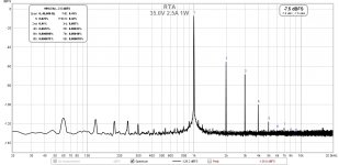
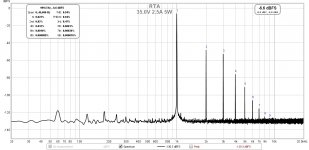
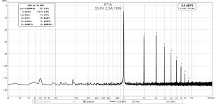
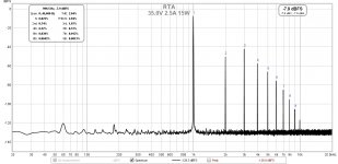
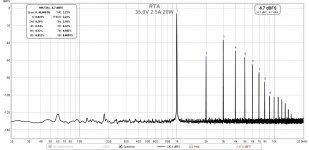
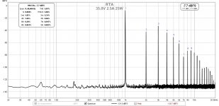
I think listening is very important to optimize amp-speaker-room interaction. Perhaps it is a good idea to try bias at 2.1A & 2.3A. In this topology different bias would yield different THD and H2/H3 ratio.Right channel FFT results:
")
Nelson Pass from The Venerable Triode Article said:In the SIT-1 amplifier from First Watt, there is a knob on the front panel and a meter for adjusting the load-line of a single SIT transistor operated Common-Source without feedback, and the user is invited to play with it. When the knob is set counterclockwise a larger amount of negative phase 2nd harmonic is present. Somewhere near the middle, the 2nd is nulled out, leaving a trace of 3rd, and when the knob is fully clockwise, the 2nd is back again, but positive in phase.
After I got enough feedback from listeners, I adjusted the circuit so that the center-point of the meter reflected the most popular position – about 1% negative phase 2nd harmonic, and made that calibration reference for the amplifier.
Last edited:
25W Single Ended Hammond 193V Choke Loaded 2SK180 L'Amp
I'm a great fan of VFETs and SITs. I've built the Papa Pass diyAudio Sony VFET amp, Michael Rothacher Sony 2SK28 Hammond 193V choke loaded L'Amp and Luminaria (2SK82) preamp, Zen Mod SissySit with THF-51S, and Pappa Pass BAF2015 amp with THF-51S. Prior to these amps, I had tubes for many years - single ended parafeed 45 amps and filament biased 26 preamp. But I don't miss those tubes. It's VFETs and SITs all the way now, thanks to Papa Pass, Michael Rothacher, and Zen Mod.
So last March when I was looking for another project,Tokin 2SK180s were readily available on ebay. Since I didn't have any amps with them I decided to buy a couple and give them a try.
I decided to use the Hammond chokes from my 2SK28 L'Amp for this project and redo the 2SK128 L'Amp in the future with a mu follower current load. The amp was built into one chassis and it was very heavy - I could barely lift it. So it went through a weight reduction, and its 193V chokes will now be transplanted to bring new life to a pair of higher powered 2SK180 monoblocks based on Michael Rothacher's choke loaded L'Amp design. I really do like the single ended sound.
Since I couldn't find much information on the world wide web on operating points for higher powered choked loaded single ended 2SK180 amps, I had to figure something out. The other factor was that Tokin SITs have a large variance in their characteristics so even computer similations would not reliably predict good operating points. Despite that I did do some LTSpice simulations for the fun of it.
Before I could do live tests to figure out the operating point that I would use, I built some chassis to mount the Tokins and keep them cool. With all my previous projects, I had purchased ready made chassis. However there was a lack of ready made monoblock chassis with a single large heatsink, so I decided to purchase some aluminum plate and angle and build my own. I don't have a work shop or drill press but I made do with hand held tools, working in my kitchen, and now I have two reasonably presentable monoblock chassis.
All circuits are point to point wired on perf board. The actual signal amplification circuit is very simple, with minimal parts. The majority of the parts are in the bias supply and in the yet to be constructed V+ supply.
To be continued.
I have built this amp with matched Tokin Vfet and been trying to find the sweet spot. The Tokin get very hot. I love the simplicity of the circuit. Thanks for the info.
Thanks for the comments, they are all appreciated
I am listening to the left channel right now, powered by the lab supply. The other channel is powered by the 2015 BAF THF-51S.
I'm enjoying the sound!
Despite the left channel not measuring quite as good as the right channel with respect to the amount of H2, I have no complaints. The H2 is still dominant at lower power output, and most of the time the amplifier does not leave that level of power.
I will probably do some tweaking once the amps are complete with their power supplies. I am still waiting for the power transformers. They are somewhere between New Jersey and Vancouver right now.
Great job Ben and thanks for sharing!!
Would you say that there is any sonic signature difference between the different SIT devices that you've tried? I'm looking for justification to add the 180s to my collection.
I know the best parts are the ones you have on hand but that life would be boring without hunting for parts now and then right?
twitchie,
I haven't noticed much if any sonic difference between the Sony VFETs and Tokin SITs that I have listened to. I do believe that there are some sonic differences due to their implementation though. I have Sonys in my diyAudio VFET amp and 2SJ28 Hammond 193V L'Amp (soon to be mu follower CS), and Tokin THF-51S in my SissySIT and BAF2015, and now 2SK180 in this amp.
The diyAudio VFET is push-pull, the SissySIT is DEF, and the 2SJ28 L'Amp, BAF2015 THF-51S, and 2SK180 L'Amp are single ended. All three single ended amps share a similar sound, and the other two are a bit different.
So the main difference is due to the implementation. The single ended amps have higher distortion with H2 dominant at lower power output. The VFET push-pull has much lower distortion and is H3 dominant. The SissySIT, also push-pull, but also DEF is H2 dominant but also lower distortion.
I prefer the sound of single ended amplifiers with their higher levels of H2.
Right now I have one channel of the 2SK180 L'Amp and one channel of the BAF2015 THF-51S playing and I don't think I would be able to tell the difference between this and having both BAF2015 channels playing.
Having said that I prefer single ended sonics, the other SIT/VFET amps that I have sound very good too. It's just fun to build more amps.
- Home
- Amplifiers
- Pass Labs
- 25W Single Ended Hammond 193V Choke Loaded 2SK180 L'Amp