that says you don't need a mat, because it is isolating . . .
That's not for the faint of heart

Just get some Keratherm sheets and be done.
I looked up the Kerafol. Mine looks very much like the grey Kerafol 86/600 Wärmeleitfoil 0.5mm 6 W/mK It says the layer has Glasfasergewebe, and mine also has the glas fiber inside.
Think I'll trust the foil then that was provided with my devices then.
Do I need extra paste? Such as Kerafol KERATHERM KP97 Koelpasta?
The devices are not super flat on the heatsink, an opening on some sides is easily 50 microns. That is, I can rock it a bit. But the "Kerafol" should damp that out.
But the "Kerafol" should damp that out.
Yes, in this respect it is much more forgiving against imperfections in both surfaces: the sink and the device.
The mechanical damping is certainly interesting. I wish someone would share sonic impressions of various sink interface materials.
thermal unstability . . .
I have one channel running in a test set. Choke-loaded, very low resistance. I take the bias from a LM7915. Potmeter 10 turns, wirewound 10K.
Required bias is about -7 volt;
The testset is with a .47 ohm resistor in the source lead. Vb = 22,5V. Very stable, 2 mV pp only on the edges of a square wave, well damped.
There is a lot of run-away - the gate current others mentioned is the cause, and that gate current is very sensitive to temperature.
Within minutes the Ids current will creep from 1.5A to 2 Amp. (at Vdrain 22V, and Vgate will move from -7V to -6.5V).
My observations:
I like to know if I am the only one with thermal run-away, and shifting operating points.
Maybe I should make an emitter follower on the bias voltage? Low impedance. The effect of the gate-current over the 5K of the potmeter will be gone.
Also use a coupling transformer with a low winding resistance.
I have one channel running in a test set. Choke-loaded, very low resistance. I take the bias from a LM7915. Potmeter 10 turns, wirewound 10K.
Required bias is about -7 volt;
The testset is with a .47 ohm resistor in the source lead. Vb = 22,5V. Very stable, 2 mV pp only on the edges of a square wave, well damped.
There is a lot of run-away - the gate current others mentioned is the cause, and that gate current is very sensitive to temperature.
Within minutes the Ids current will creep from 1.5A to 2 Amp. (at Vdrain 22V, and Vgate will move from -7V to -6.5V).
My observations:
- the 2SK182 case gets hot, not the heatsink. Only after one hour does the heatsink get warm (some 40-50W dissipated); the Tokin does get hot.
- When I put my finger on the case, the drain curent relaxes and thus gate current drops.
- gate current was measured at 50 micro amps (one volt on the 20K), and it can easily double - similar as others mentioned, and rises quickly with temperature; so the bias drops fast. Even with a transformer winding as gate-load it changes, but slowly, due to the resistance of the potmeter.
- A 20K bias resistor is too large; a transformer winding as load is OK.
- So even the 10K potmeter I use for bias level with effective resistance of about 5K gives too much of a voltage drop (that is rise of the negative bias)
- with the abundant PTC, the effect can be desastrous.
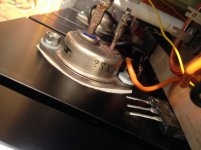
- It looks like there is not a good contact between house and SK109 heatfin. I use a grey Kerafoil [look-alike] I got from the vendor, without extra goop.
-I have observed that I could rock the house a bit on a flat surface, so not perfect flat. Use a sheet of lead, I heard you say faintly in the distance. - There is no HF oscillation I can see on my tektronix 475 / 200Mhz. But I probably should insert a Zobel 100nF/22 ohm anyway between drain and source.
I like to know if I am the only one with thermal run-away, and shifting operating points.
Maybe I should make an emitter follower on the bias voltage? Low impedance. The effect of the gate-current over the 5K of the potmeter will be gone.
Also use a coupling transformer with a low winding resistance.
Attachments
I'll tomorrow make a DC buffer with a PNP-transistor and use transformer primary as load; and put second channel under power.
Do you use mica for the big ones??
Do you use mica for the big ones??
also prefer SIT bottom sanding on wet sanding paper on glass plate ... if using mica , of course
for silicon pad , no need for SIT bottom plate sanding
I use a grey Kerafoil [look-alike] I got from the vendor, without extra goop.
Pras supplies some grey horror with the sits. It is completely useless for this application. Get proper Keratherm, it's a night and day difference.
The worst of my 2SK180 also had a gate leakage current of over 50 uA as I noted in posts in this thread. It caused me much grief.
With high gate leakage current, 20K resistor at gate to bias supply is too large. I used 10K and even that was too high, causing substantial drop in Vg as the gate leakage current increased with temperature. So perhaps even 5K might be worth trying? Or a low DCR grid (gate) choke.
I ended up with 0.6R at the source and that helped offset the drop in Vg. That worked reasonable well except when the line AC voltage fluctuated and went higher than normal. That resulted in rising temperature and increase gate leakage current and higher drain current again.
So I ended up with bias and Iq set for stability during the worst possible conditions. That meant that at any time the line AC voltage was not at maximum and temperature was not at maximum, the amplifier was not operating at the target Iq. I tried regulation in the V+ supply but that meant a drop in the V+ and different operating point. The previous addition of source resistance had already lowered Vds so this was an additional hit.
As noted in previous posts I changed to common drain due to frustration. With the choke (1 Ohm DCR) at the source, the Vs increased as the drain current increased and that helped offset the Vg decrease due to the gate leakage current, and provided stability. The minus was it still took a long time for the amplifier to get up to temperature. As with common source, because the bias was set for the final condition accounting for the drop in Vg due to the rise in gate leakage current, the initial Vgs at start-up was high resulting in low drain current. The drain current would increase as the gate current increased, and it would take over two hours for the amplifier to reach final temperature and drain current.
The big plus was I preferred the sound of common drain.
In the end I purchased another 2SK180 to replace the leaky 2SK180. The new 2SK180 had lower gate leakage current so the bias voltage did not drop as much due to temperature, resulting in a much faster warmup and much smaller change in Iq.
Unfortunately there is a lot of variability among Tokins.
Channel B is up, I started now with a 4 ohm as drain, not choke. Once I saw that was good, inserted the choke in the loop. Stable 1.3 amp for a over 30 mins, heatsinks stay cool. -3dB: 8 Hz to 67 KHz. Very nice.
I'll try to get an other SIT for the A channel. Maybe two - to select a matching one. And I've found 50x50mm mica in the Big Red Wherehouse. Will take some time.
Wherehouse = Wherisitwarehouse? WhereisdeSITwarehouse? Hope I don't have to wait too long.
I'll try to get an other SIT for the A channel. Maybe two - to select a matching one. And I've found 50x50mm mica in the Big Red Wherehouse. Will take some time.
Wherehouse = Wherisitwarehouse? WhereisdeSITwarehouse? Hope I don't have to wait too long.
It is worth checking that the insulating shoulder washers (Nylon bushings ?) are actually a little bit shorter than the thickness of the Tokin flange, so that you can apply proper pressure on Tokin towards heatsink.
I did cut a bit off my insulating washers to have them shorter than the flange ...
Regards, Claas
I did cut a bit off my insulating washers to have them shorter than the flange ...
Regards, Claas
yup, logical and normal procedure
one without wire eyelet - put it in hole, cut protrusion with xacto
other with wire eyelet - place it together with eyelet in hole, cut protrusion with xacto
don't mix them later
if torquing with proper force (say 1.5Nm is OK for M4 taking in account all sorts of thermal pads), there is no much squish force, if plastic bushing is too long
Great remarks; I did cut it off a bit (but not in ZM's smart way); but what I did, is drill (dia 5mm) in the tapped hole a mm or so in order that the whasher ring would protude in the sink. I do see the problem of it squeezing out and prohibiting a good contact. This just to prevent any metal to touch base.
[test with a glass plate . . . ]
[test with a glass plate . . . ]
Took the whole apart, now use mica's. Indeed, the rings was protruding slightly (but I had resesses), but worse, the sheet of heatsink stuff was folded at the screwmount on one transistor . .
So what is giving the evident oscillation that I can't even see on my scope in the 200 MHz setting?? Several members have reported on this type of tipping point in examples of the 2SK182{E}.
I looked at the case/heatsink capacitance. It is 350 pF drain/earth, in parallel with the choke. capacitance in the gigaherz region? Should I make a Fraraday cage around the SITs (I saw someone had hade a small metal box . . in a jig for testing 2SK182's)?
The other channel is OK.
The vendor is sending a replacement part, very kind by the way. Will take some time.
- So previously I had gate current already starting at 50 mA DC; even with a secondary coil of a 2k4 transformer. In the first mounting the fit of the case on the sink was bad; I filled the back down to even flatness on a whetting stone
- I note yesterday the failing SIT now remains longer stable, I could turn it up to 800 mA.
- This morning, I took the heatsink off the amplifier base. [To see if the case/sink capacitance was the culprit]. No, but turning slowly at 70 mA I could see the output (at 2x ampl); the instability was there too then. I could now touch the house (=drain) and the amplification would drop just like the current; I could also see the gate current changed a bit.
So what is giving the evident oscillation that I can't even see on my scope in the 200 MHz setting?? Several members have reported on this type of tipping point in examples of the 2SK182{E}.
I noted at a certain moment that when I had my hand close to the SIT to turn the bias pot, the oscillation would change and even disappear - seen in a going down of the DC, say from 1 amp to 900mA; taking my hand out, it would pop up again and rise.
I looked at the case/heatsink capacitance. It is 350 pF drain/earth, in parallel with the choke. capacitance in the gigaherz region? Should I make a Fraraday cage around the SITs (I saw someone had hade a small metal box . . in a jig for testing 2SK182's)?
The other channel is OK.
The vendor is sending a replacement part, very kind by the way. Will take some time.
Last edited:
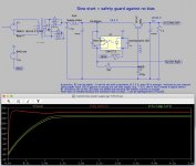
Slow start to give bias the time to settle
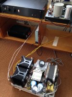
I wanted to share my thiughts about a minimalistic power supply for the L'Amp.
It has a safety net in the form of the optocoupler. (4N35 is OK)
It only allows passing of current to the drain of the SIT IF the bias voltage is there.
Slow start; without the opto, the unit fires up in 0,5 sec.
Both channels have their own cap-multiplier/that is, a TIP147.
I have not made the opto-part yet; the rest is fully working and in practice 2 to 3K for the base is enough (I used a potmeter to set it; both TIP147 transistors Left and Right differ in the current amplification factor).
I wanted to share my thiughts about a minimalistic power supply for the L'Amp.
It has a safety net in the form of the optocoupler. (4N35 is OK)
It only allows passing of current to the drain of the SIT IF the bias voltage is there.
This precaution is important, as having drain voltage before bias will melt a SIT; I am afraid. Anyway, maybe not th real reason for the death of SITs on the test bench, but such a logical error state is avoided now.
Slow start; without the opto, the unit fires up in 0,5 sec.
Both channels have their own cap-multiplier/that is, a TIP147.
There is no difference I see between TIP122 and TIP147, the latter is more sturdy.
In practice, the pass transistor does not heat up; I bolted it to the cabinet.I have not made the opto-part yet; the rest is fully working and in practice 2 to 3K for the base is enough (I used a potmeter to set it; both TIP147 transistors Left and Right differ in the current amplification factor).
Attachments
Last edited:

A new Ch'amp arrived
I finished my Ch'amp build.
Firstly, because one SIT is leaky, I went for DC coupling. The 2SK170/2SJ74 buffer is biased to the potmeter, 220k and 150nF. This works well.
I had to reduce the V+ to balance the power supply of the buffer a bit.

Current is stable both channels with the DC buffer, over several hours as the heatsink heats up to ~45 degrees [25-23V/1.2-1,5 amp]
Channel balance 0,5 Db - I can't hear that.
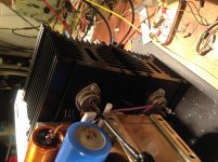
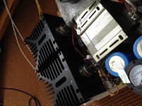
My choke is 0,5 ohm Rdc. BIG BIG thing in the middle.
Sweep goes 7 Hz to 68 KHz. Rising edges without any sign of oscillation.
WOW. The sound has a slightly better stage to the back than my 300B. Sound from well-mixed sources are everywhere, great. Great lows and soft highs. [My F5 has fine highs but less bass, having high feedback and lower DF of course]
Rich harmonics. Voices are tangible. Many layers.
Max 8 watts - due to one channel getting a slight top edge. I have to increase the voltage, as you see I have enough taps, now using three 7.1 V taps, have 5 total; and one 4 V, all thick 1 mm wire. But the blue caps are only 20.00uF/25V so I have no room now to increase now, must wait.
No sound in the speaker what so ever from the line. Nor from starting or stopping.
Improvements:
New power line caps. To allow me up to >30 V.
Now output cap is 2.200uF/63, move to 5.000mu that I took out when I noticed one channel had the house connected to the neg pole from a bump; but with a washer this will be OK.
I can develop into a MU-follower, but to use that I need a printed circuit.
My idea of a solid state relais with the 4N35 is not needed . .
I finished my Ch'amp build.
Firstly, because one SIT is leaky, I went for DC coupling. The 2SK170/2SJ74 buffer is biased to the potmeter, 220k and 150nF. This works well.
I had to reduce the V+ to balance the power supply of the buffer a bit.
Current is stable both channels with the DC buffer, over several hours as the heatsink heats up to ~45 degrees [25-23V/1.2-1,5 amp]
My earlier initiative with an emitter follower 2SA1015 I used with a CCS @ 5 mA was stable, was not good enough: slow rise time, slow fall time. [I know, charging an 8nF gate charge is not a simple thing]
Channel balance 0,5 Db - I can't hear that.
My choke is 0,5 ohm Rdc. BIG BIG thing in the middle.
Sweep goes 7 Hz to 68 KHz. Rising edges without any sign of oscillation.
WOW. The sound has a slightly better stage to the back than my 300B. Sound from well-mixed sources are everywhere, great. Great lows and soft highs. [My F5 has fine highs but less bass, having high feedback and lower DF of course]
Rich harmonics. Voices are tangible. Many layers.
Max 8 watts - due to one channel getting a slight top edge. I have to increase the voltage, as you see I have enough taps, now using three 7.1 V taps, have 5 total; and one 4 V, all thick 1 mm wire. But the blue caps are only 20.00uF/25V so I have no room now to increase now, must wait.
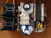
I have CLC-CM-C (12.000uF - 2 mH/0.1 ohm - 13.000 uF - TIP142 - 20.000uF.
The rectifier is a big metal KBC, but the drop across it is very high. It crying out for a LT4320 . .
The cap multiplier works well: I have a 3 mA CCS in the base current feed, makes for a very slow start (1-2 sec), great, no plop, and when working, the TIP142 in each channel is fully saturated with the current, Hfe being about 1.000.
The scope gives a pure 100 Hz sine before the CM.
No sound in the speaker what so ever from the line. Nor from starting or stopping.
- Yes, the subwoofer jolts at turn-off, and goes into emergency mode/blinking. There might be a reverse discharge across the 150 nF input cap that I do not understand
 ; the preamp being DC and having ample feedback and bandwith; have not had that before.
Improvements:
New power line caps. To allow me up to >30 V.
Now output cap is 2.200uF/63, move to 5.000mu that I took out when I noticed one channel had the house connected to the neg pole from a bump; but with a washer this will be OK.
I can develop into a MU-follower, but to use that I need a printed circuit.
I was contemplating hacking the ACP+ board for such use, add a -5V bias setting, then it will be a RUDNESSIT (che nessuno comprende) but LTSpice still does not approve that idea, does not understand it and often enters in long loops, so rude that feedback, it's not fair . . .
My idea of a solid state relais with the 4N35 is not needed . .
Attachments
Last edited:
- Home
- Amplifiers
- Pass Labs
- 25W Single Ended Hammond 193V Choke Loaded 2SK180 L'Amp