I have no clue wrt speaker selay/protection circuits so can’t help. But might be smart. A friend is an EE, repairing some amps now that killed really expensive speakers. No protection circuit, DC from pre killed the speakers.
Didn’t see your question about the beast. Had that hum, almost gone but bugs me still. Then there is some bias variations, too high bias and rails combined with low source resistance. No good combo. But sounds great. But still.
Plus I wanna make it look the part. So that’s basically it =S
Didn’t see your question about the beast. Had that hum, almost gone but bugs me still. Then there is some bias variations, too high bias and rails combined with low source resistance. No good combo. But sounds great. But still.
Plus I wanna make it look the part. So that’s basically it =S
Last edited:
Argh. Anyone reading this? I mean: AARGH!
Or even better yet: Monty Python and the Holy Grail black beast of Arrrggghhh - YouTube
The whatnot causing headaches? Me Debugging-wannabe-expert? HA!
After reunsoldering the little hack I made to see if it’s working in the basic construction and even one more loop, uhm, well, why not hook-up the transfo just so to see if things improve?
Selfslap for about a week [emoji1787]
Ok then, so.
Apologies for my ignorance and confusion.
I tried to make a sketch how everything is connected, and afaik it’s all there (haven‘t forgotten anything).
I not able to draw it as a true scm, so it’s a bit of a kindergarden attempt...
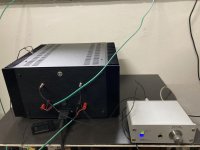
the 2 Fotos show:
1) The connection from the mains (after the switch) into softstart resp. to speakerdelay. (The speakerdelay is not connected to the softitart-board but just uses it as connection-point. This looks confusing, I did it for lazyness)
2) The connection FROM the softstart TO the toroid's primaries. (Paper is there for visibility)
PS: I had all PSU-parts already switched on, everything seems fine so far: Softstart engages (quick, may need a longer delay), PSU gives 24.8V I believe... Speaker-delay got tested under the sharp eyes of mooly, all good there.
(Please don't read this: Basically, I'm confident it is all well here)
Took a look at your schem. If you have hum, Try connecting OS 0vs to the same gnd point on the PSU, as close as possible. Also you can try twisting wires to binding posts, and wires to and from PSU. Include 0vs. Also, ensure chassis gnd is properly connected to PSU gnd. Keep this connection closer to the gnd links than the OS 0vs, and tighten good if not soldered.
Also, you could try to lengthen the tranny screen/gnd wire and connect it to star gnd/chassis gnd.
And like ZM had said before, ensure all AC wires including secondaries are properly twisted and as close together as possible to reduce loop areas.
If you have no hum, disregard
Regards,
Andy
Last edited:
Aah, sorry friends, I shouldn‘t have mentioned loop—it was a needless screw-unscrew-loop, not an electrical one.
I was the problem. First forgot to hook up the device (like in debugging procedure, step 1: make sure the device is hooked and power is on.)
Then there was a defective or unconnected wire-bracket (those plastic-plugs to screw the wire in.) Just had to switch position.
But now it’s looking good again, baby is warming up...
Apologies for my useless chatter, I thought I‘d try with whining instead of bragging [emoji16]


Me too! You are almost at the finish line.
On mine, I set up the bias to 200mV and made sure it was stable, then adjust offset. Adjust bias to 225mV and re-adjust offset after two hours. Satisfied with the current setting and measurements, left the amp with the setting for about two weeks while being use. Re-adjust bias to 275mV, checked dc offset, then that's it. Re-install top plate, done,
On mine, I set up the bias to 200mV and made sure it was stable, then adjust offset. Adjust bias to 225mV and re-adjust offset after two hours. Satisfied with the current setting and measurements, left the amp with the setting for about two weeks while being use. Re-adjust bias to 275mV, checked dc offset, then that's it. Re-install top plate, done,

Here we go!
The almost last 5mm (make connectors) went very easily.
Plugged it in, and was a bit worried if everything would really be ok?
Nothing on power on, and then... a very strange new way of sound-impression coming out. I had a audiolab 8000C + P, a Onix 21, and a DCB1/ACA combo playing, and now its a furutech gt40 and that F4, which is warming up. I start to like it (30°C heatsink)...
Mr. Pass, 6L6, mighty ZM, Mooly, Dennis, 2Pico (bloody), itsallinmyhead, and the ones I forgot, many many many thanks!
The almost last 5mm (make connectors) went very easily.
Plugged it in, and was a bit worried if everything would really be ok?
Nothing on power on, and then... a very strange new way of sound-impression coming out. I had a audiolab 8000C + P, a Onix 21, and a DCB1/ACA combo playing, and now its a furutech gt40 and that F4, which is warming up. I start to like it (30°C heatsink)...
Mr. Pass, 6L6, mighty ZM, Mooly, Dennis, 2Pico (bloody
), itsallinmyhead, and the ones I forgot, many many many thanks!Attachments
Last edited:
Next steps...
the next steps (mechanical bragging stuff):
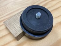
modushop‘s antivibration feet are bugging me, dont like the plastic and especially I‘m not convinced of the fact that they‘re supposed to be attached to the 2mm baseplate, it _will_ bend!
How did you do it?
Then, getting the faceplate done. Sorry, ZM, no lenco-logo, I‘m on thorens and won’t even put this one on 😊...
The power-switch is also a little bit a challenge, have to lower the torque and have it sound better (it’s too hard to turn and sounds clicky.
...
the next steps (mechanical bragging stuff):
modushop‘s antivibration feet are bugging me, dont like the plastic and especially I‘m not convinced of the fact that they‘re supposed to be attached to the 2mm baseplate, it _will_ bend!
How did you do it?
Then, getting the faceplate done. Sorry, ZM, no lenco-logo, I‘m on thorens and won’t even put this one on 😊...
The power-switch is also a little bit a challenge, have to lower the torque and have it sound better (it’s too hard to turn and sounds clicky.
...
Attachments
The GT40 is a dac/headlamp/preamp, with a phono-input, by ADL/furutech...
Looking up 6L6‘s way now. But the construction is a bit contrary to how static forces are applied. (I also don‘t quite agree with other details of the chassis construction, but won‘t complain, they‘re still really nice).
And, I believe that Jim‘s feet are different: Mine have the screws embedded in the rubber so there‘s no way to get to the steel-bracket (clamping the baseplate between foot and bracket is not an option)
Last edited:
- Home
- Amplifiers
- Pass Labs
- My F4 build (questions, bragging, and other thoughts)