Re: schematic in post #597
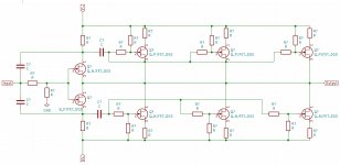
Since your push pull output drivers have their gates AC coupled to the input stage, you'll need some sort of a biasing circuit to set the DC value of the gate voltage. Look at the NJFET at bottom right: its gate is completely floating and has no DC path to either supply rail.
You might even decide to build two biasing circuits. One to establish the correct DC bias current flowing in the upper half, and another "DC servo" to establish whatever DC bias current is needed in the lower half, to make the output offset voltage become zero millivolts.
Hello Mark. Thank you for your feedback. The initial idea is to use the JFETs at Idss (or as close to as possible and select the groups for a close match. The JFETs that I have in hand have Idss grouping in the neighborhood between 5:4 and 6:4. The PBC may be populated in that ratio with some not populated to balance output offset voltage.
Thank you for pointing out the floating nodes. I have added the gate reference resistors.
Attachments
all roads are leading to Rome")
Nah, scrape it, this one is a toll road, too expensive in terms of voltage: the double MOS current mirror is using up too much of it. Of course, it's originally designed as an HPA.
not exactly
gnd ref resistor for input, not really necessary
few shorts (G-D upper Jfets), just omission
and, you need just one gate ref. resistor for all JFets on same rail
Thank you for the help. Here are the corrections. The input ref resistor can be non-populated if the builder wishes.
I will see how many of these can fit on a 100mm x 100mm PCB and build one. The resistor values can be played with to see what works.
Attachments
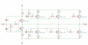
...too expensive in terms of voltage: the double MOS current mirror is using up too much of it...
Swap the mirror FET's for BJT's (BC327/337-40) and use 100R & 50R emitter resistors.
I'd also move the feedback to the top end of R4.
45V is too high for the JFET's, you'll need to cascode them.
Swap the mirror FET's for BJT's (BC327/337-40) and use 100R & 50R emitter resistors.
I'd also move the feedback to the top end of R4.
45V is too high for the JFET's, you'll need to cascode them.
Thx for the hints.
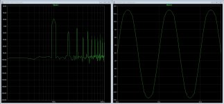
I pick the UTHAiM on a whim, but I don't feel comfy with this topology: the original UTHAiM fed with +/- 24V starts clipping at about 16V peak, with all harmonics present.
Maybe I'll explore the F5 as a FE, or even something more buildable like the MP150/Goldmund FE, we'll see. No offence, but I don't like the BA3.
Attachments
For those interested, Nelson sent me this email today with regards to max rail voltage for the Stasis FE pcb - as per his design he recommends max rail volts as +/- 60VDC.
Nelson quotes:
"Whatever the transistors are rated at for voltage. I recall the ones I have around here are 120V, so +/-60V is likely the limit. You have to
watch the bias currents as the dissipation on the transistors can get
high. For the big sink Vas parts I wouldn’t want to exceed about 15 mA
at these voltages."
:end quote.
Regarding rail voltages, found the following quote:
Radioactdave:
Nelson knows these IR parts inside and out. The operating voltage is always
matched to the the part having lowest possible gate capacitance for example,
same goes for operating temperature.

The Stasis SA3 has numerous avid fans, and it appears that one of the main differences was that it was strictly class A.
If we don't need the power of A/B, is it fairly simple to tweak the new FE it to be class A?
Or even better, a switch or two that would allow us to go back and forth?
If it's possible, add me to Zen Mod's "spoon-feed-me" list, and provide as many details as you have patience for...thanks!

If we don't need the power of A/B, is it fairly simple to tweak the new FE it to be class A?
Or even better, a switch or two that would allow us to go back and forth?
If it's possible, add me to Zen Mod's "spoon-feed-me" list, and provide as many details as you have patience for...thanks!
that's just matter of carefully chosen rails, resistor values in OS and how far you're going with bias trimpot crank
FE is pretty much not caring how much you gonna sweat OS stage
though - remember that I said I'm gonna be armchair Dodo Expert this time, Mighty Moi not going to build Stasis
FE is pretty much not caring how much you gonna sweat OS stage
though - remember that I said I'm gonna be armchair Dodo Expert this time, Mighty Moi not going to build Stasis
In a message from Nelson - heaps of heatsink, plenty of PSU capacitance and crank up the bias to give you 50 deg C on the heat sinks after an hour, and you will have all the magnificent pure class A watts you want. Adjust your +/- DC rails to give you the required total watts RMS - simple.
I am not going "over the top" with my build. 800VA toroid (2 x 30VAC secondaries) to give +/-40VDC rails, using LT4320 active rectifier, with approx 60,000 uF supply capacitance per rail per channel (240,000uF total). Using the 8 pair ZM OS pcb and Nelson's new FE pcb. 4u x 500mm deep pico chassis. Biased to around 45 to 50 deg C on top part of heatsink. Extras will include a mains soft start board and XRK's SSR solid state speaker pcb per channel. Plenty of room in that chassis for all those parts.
- Home
- Amplifiers
- Pass Labs
- New Stasis front end