Thanks for all of your work ZM! How easy will these be to implement into an amp like the s/500?
though .... if your amp is functional, it'll be best to ask Pa - is expected change in sound quality worthy of expected hassle?
point is - for someone with extensive mileage, transformation should be easy and fun and risk-free, so every improvement worthy
I'm guessing now, but I believe that - for someone in need to ask about - lack of mileage is most probable fact, so risk is greater and possibility to end with enormous pile of dead semis not really ignorable
The amp works great. I will see if he gets a chance to respond. I just ordered the F6 parts from the DIY audio store and mouser so I am sure I will be captivated by that for a while.
In an old thread he had mentioned that an upgrade that could be done to the S/500 would be a front stage that never made it out before he had left Threshold. Not sure if it was implemented at all in this new design.
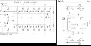
Theshold S500II
I do love the Stasis lineup. They look unassuming until you really look at them. Great chassis, excellent layout, everything is neat and tidy. NP and his accomplices really outdid themselves.
In an old thread he had mentioned that an upgrade that could be done to the S/500 would be a front stage that never made it out before he had left Threshold. Not sure if it was implemented at all in this new design.
Theshold S500II
I do love the Stasis lineup. They look unassuming until you really look at them. Great chassis, excellent layout, everything is neat and tidy. NP and his accomplices really outdid themselves.
I'm making some progress on this amp. Have the PCBs populated except for the stuff I forgot to order (old age setting in...). I have a couple minor questions. I thought they were answered earlier in the thread but I can't find the answers and I didn't write them down when I first saw them.
1. What is the purpose and recommended value for C5?
2. Does the 2K NTC thermistor want to be mounted on the heatsink?
Thanks.
1. What is the purpose and recommended value for C5?
2. Does the 2K NTC thermistor want to be mounted on the heatsink?
Thanks.
1. Pa sez - none, for now an with his FE pcb; Greedy Boy with scope should check that, for tiny pcb, just in case
2.yes; drool on pics in post #1 ; I mean - you need to mount it on OS heatsink, some place with steady high temp, while I really can't be sure what actual NTC want ..... it probably depends of type of NTC, maybe even of actual personality of same
2.yes; drool on pics in post #1 ; I mean - you need to mount it on OS heatsink, some place with steady high temp, while I really can't be sure what actual NTC want ..... it probably depends of type of NTC, maybe even of actual personality of same
Last edited:
Looks like the center of the heatsink should be a good place. I'm going to see if I can find the NTC that has an eyelet to make it easy to mount.
So C5 is for oscillation? I can put the FE on a scope and take a look. I assume it can be checked without connection to the OS - correct? (showing my ignorance).
So C5 is for oscillation? I can put the FE on a scope and take a look. I assume it can be checked without connection to the OS - correct? (showing my ignorance).
Transform BA3 to Stasis?
Forgive me is this obvious to most people.
It occurs to me that if, in the BA3 preamp, you connect R5 to output instead of being connected to ground, you now have a stasis BA3 preamp. Maybe R5 becomes smaller, maybe zero ohms.
Forgive me is this obvious to most people.
It occurs to me that if, in the BA3 preamp, you connect R5 to output instead of being connected to ground, you now have a stasis BA3 preamp. Maybe R5 becomes smaller, maybe zero ohms.
Attachments
practically - BA3 FE is, well, FE;
while Stasis FE is FE with bias generator for OS
Stasis catch is in OS, so - pretty much any sort of FE is appropriate, as long bias generator is there
not counting on fact that you'll need to alter value of that resistor, accordingly, to include it in NFB loop, instead of acting as local degeneration thingie
The idea would be to create a new stasis OS topology with the devices in BA3 preamp. Just a mental exercise to see if I understand the stasis OS.
It looks to me that the stasis OS is unity voltage gain with very large current gain. 100% local voltage degeneration in the OS using what looks like "current feedback".
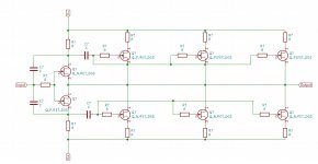
The next idea is how to make a stasis OS using 1000 JFETs. I think a blocking capacitor is needed for each cell because the JFETs are self-biased.
It looks to me that the stasis OS is unity voltage gain with very large current gain. 100% local voltage degeneration in the OS using what looks like "current feedback".
The next idea is how to make a stasis OS using 1000 JFETs. I think a blocking capacitor is needed for each cell because the JFETs are self-biased.
use BA3 FE, build OS bias gene as separate/add on
easy peasy
though , take care about rail voltage, if plan is to go above recommended for BA3 FE (JFet cascoding if needed)
regarding zillion JFets ........ I'm too old for that and , frankly, too loaded with other exotic parts to go that route
easy peasy
though , take care about rail voltage, if plan is to go above recommended for BA3 FE (JFet cascoding if needed)
regarding zillion JFets ........ I'm too old for that and , frankly, too loaded with other exotic parts to go that route
use BA3 FE, build OS bias gene as separate/add on
easy peasy
though , take care about rail voltage, if plan is to go above recommended for BA3 FE (JFet cascoding if needed)
regarding zillion JFets ........ I'm too old for that and , frankly, too loaded with other exotic parts to go that route
Here is what I am thinking for stasis JFET beast. This drawing is 3 cells representing hundreds or thousands.
Attachments
I'm sure this will earn me an immediate and well deserved excommunication.
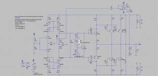
EUVL's UTHAiM FE with the Stasis OS: it sims OK.
I would like little more current from FE at disposal
So, I would change that, in some way
Here is what I am thinking for stasis JFET beast. This drawing is 3 cells representing hundreds or thousands.
yup, just solve half of those question marks, and you're good
I will be grateful
")
Re: schematic in post #597
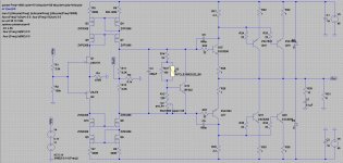
Since your push pull output drivers have their gates AC coupled to the input stage, you'll need some sort of a biasing circuit to set the DC value of the gate voltage. Look at the NJFET at bottom right: its gate is completely floating and has no DC path to either supply rail.
You might even decide to build two biasing circuits. One to establish the correct DC bias current flowing in the upper half, and another "DC servo" to establish whatever DC bias current is needed in the lower half, to make the output offset voltage become zero millivolts.
I would like little more current from FE at disposal
So, I would change that, in some way
Good eye: it was running at about 7mA. Now it's at about 17mA, and I added back the DC servo because the offset is a bit high. I sort of like this Frankie
Attachments
- Home
- Amplifiers
- Pass Labs
- New Stasis front end