I am sure you could make it fit however if you wanted to try it out.
Of course! This statement was for the benefit for those considering upgrading or repairing an original.
Otherwise, it is a lovely and somewhat simple recipe to build yourself one hell of an a/b or whatever amp. Pretty cool!
Who is gonna run some boards this side of the pond? In blue and gold of course.
")
Last edited:
make a consensus about type of outputs, OS arrangement, max number of devices per channel (UMS applicable?) and I'm going to draw OS pcb for Greedy Boyz
Thank You Zen Mod!!
If the T.Masculinity case doesn’t fit the normal UMS, there’s little reason to continue with that case until it does.
But that case would be perfect for this!!!
It fits all UMS pcbs, but also more.
I suggest you start a GoFundMe page to pay ZenMod for his time and expertise. You couldn't possibly hire a consultant with his level of experience for less than $100 per hour. I did the Store's M2x and based on that, I estimate Zen Mod will require about 50 hours to design the circuit, enter its schematic into the CAD system, enter the PCB footprints of the unique new devices into the CAD system, lay out the PCB, and create the Gerbers.
For $5000 I'm sure he would calmly listen to your nonstop and endless list of "just one more feature" requests.
For $5000 I'm sure he would calmly listen to your nonstop and endless list of "just one more feature" requests.
Tnx Mark for encouraging words
however, I'm still ( and always be) dumber than Pico, and Pa taught me how to be faster and cheaper, especially when not being paid
if memory serves me well, UMS is allowing up to 8 pairs of outputs?
I have it somewhere, but it can't be hard to find on Store pages
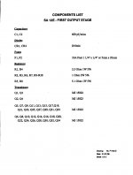
in any case, I'll ask Pa to fill me with parts values, especially considering Q1 and Q2 types, once when Boyz decide what's preferred type of outputs
and even that - why should I care, TO-3P/TO-247 is all I need as info
going to zzzzzzz a little .........
however, I'm still ( and always be) dumber than Pico, and Pa taught me how to be faster and cheaper, especially when not being paid
if memory serves me well, UMS is allowing up to 8 pairs of outputs?
I have it somewhere, but it can't be hard to find on Store pages
in any case, I'll ask Pa to fill me with parts values, especially considering Q1 and Q2 types, once when Boyz decide what's preferred type of outputs
and even that - why should I care, TO-3P/TO-247 is all I need as info
going to zzzzzzz a little .........
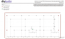
UMS - https://cdn.shopify.com/s/files/1/1006/5046/files/universal-mounting-specification-v2.1.pdf
Big UMS is 6 pairs.
Big UMS is 6 pairs.
just one addendum before zzzzzzz, which is giving most answers I need for making that pcb
arrangement is pretty much 1+7 pairs, ubergovernor transistors (Q1 and Q2) being of same type as rest of them .......
this page is very informative, besides note that Iq of each outer Q is in range of 20-50mV across 1R emiter res, or usual 45-55C on sinks, whatever comes first
OK - Iq info in this moment highly debatable, I'm really sleepy
two most informative pages in this moment :
excusssse for my lack of energy for shrinking.....
edit: UMS pdf is here: https://cdn.shopify.com/s/files/1/1006/5046/files/universal-mounting-specification-v2.1.pdf
since 300deep chassis is for Sissies only, excuse me that I'm really insisting in arrangement for 400 deep, which complies with (1+7)=8 output pairs
is there any other choice , if going for 1R emiter resistors?
Attachments
Last edited:
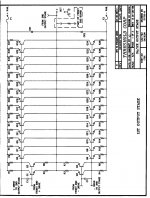
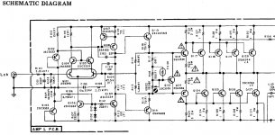
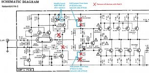
I own a first gen Nakamichi PA-5 and decided to look at the differences between the revised Stasis circuit from Nelson and the original Nak PA-5 to see how big the changes were. After a bit of evaluating the boards and new circuit it would actually be very little work to revise the original Nak pcb's to the new revised Stasis circuit. The hardest part would be adding the pair of 1k divider resistors (R14/15 in the new circuit) to the base of Q107 in the old Nak pcb. I attached the original Nak circuit & my MS Paint edited schematic. The nice thing about the Nak pcb's is that they have a fair amount of space on them to allow for modifications. The stock pcb's would be even simpler with the reduction of parts.
In addition to my edits, various resistor values can be updated. Add the miller cap across R109 and the electrolytic cap across the bias network. Swap out C103 originally a 22pf for a 33pf.
The original Q108/Q109 (SA1321/SC3334) could be swapped out for the KSA1381/KSC3503 as the pinout is the same.
Did I overlook anything?
Attachments
Last edited:
The Nakamichi also has a 75C temp switch but its part of the protection circuit.
It could be relocated to shut down the front end current source as Nelson's revision shows or it could just be left alone in the Nak.
The thing with the Nak amps is that they do not have a separate output stage board. The input and output stage are all built into the one board. This is the reason I was looking at a way to do the revision to the original board. The nice thing is that the changes that I see to the original board could easily be reversed.
- Home
- Amplifiers
- Pass Labs
- New Stasis front end