
Pa didn't tell that he remembers time when toobz were made for 6V battery anode circ
that's the reason why common name for rail is Ub

( I knew that reason for cascode stage, believe info came from Pa, but wasn't even contemplating about cascode OS, having other occupations)
that's the reason why common name for rail is Ub
( I knew that reason for cascode stage, believe info came from Pa, but wasn't even contemplating about cascode OS, having other occupations)

Obviously very conservatively rated - so will last a lifetime.
Mr Pass, that leads me to a question on the selected output devices, I see you have used the On Semi MJ21193/94 types with an fT of 4MHz and Cob of 500pF. I see Nakamichi for the PA5 (same O/S as the Stasis) used Sanken 2SC3263/2SA1294 with an fT of 60MHz and Cob of 250pF. Their voltages, currents, HFE and power ratings are similar.
Do you see any reason not to use the Sanken devices for the Stasis output stage- just asking as I have these here, thanks.
Gary..
Last edited:
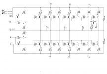
Based on Zen Mods output stage and pcb layouts, one can shoot for the following output power's with the DC rails as shown, when biased roughly as per the original Threshold Stasis biasing instructions - or by setting the bias to achieve a maximum of 50 deg C at the hottest part on the OS heatsinks - give or take a few watts.
42 watts = +/-30VDC rails.
50 watts = +/-35VDC rails.
57 watts = +/-40VDC rails.
65 watts = +/-45VDC rails.
70 watts = +/-50VDC rails.
78 watts = +/-55VDC rails.
85 watts = +/-60VDC rails.
93 watts = +/-65VDC rails.
100 watts = +/-70VDC rails.
42 watts = +/-30VDC rails.
50 watts = +/-35VDC rails.
57 watts = +/-40VDC rails.
65 watts = +/-45VDC rails.
70 watts = +/-50VDC rails.
78 watts = +/-55VDC rails.
85 watts = +/-60VDC rails.
93 watts = +/-65VDC rails.
100 watts = +/-70VDC rails.
Power in W is V^2/R load
V are RMS.
50V rails will probably hit 42V maximum swing at high power because of the 1R emitter resistors.
42*.707 = 29.69
29.69^2 = 793
793/8 = 99 W
The same with 65V rails (57V swing, 40.3Vrms) gives an output of 200WPC into 8R...
Again, it is worth considering my previous admonition -
V are RMS.
50V rails will probably hit 42V maximum swing at high power because of the 1R emitter resistors.
42*.707 = 29.69
29.69^2 = 793
793/8 = 99 W
The same with 65V rails (57V swing, 40.3Vrms) gives an output of 200WPC into 8R...
Again, it is worth considering my previous admonition -
As rails go up and current increases, it becomes easier and easier to let the magic smoke out with excitement and vigor.
Last edited:
Thanks Jim for the input, I was basing my rough calc's on the published Stasis Biasing specs from some time ago. Was just a rough guide for members. I will be sticking to around 40VDC rail voltage - plenty of power for me.
For instance the SA/3 had +/-34VDC rails for a power rating of 50 watts with a bias voltage of 200mV hot across the emitter resistors.
For instance the SA/3 had +/-34VDC rails for a power rating of 50 watts with a bias voltage of 200mV hot across the emitter resistors.
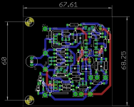
FE + OS pcbs package
OK, wasn't that much alleluia moody, but I know Pa have these days some other things to think of, so here it is ....... maybe some work shaven from his pile
(Pa - remember that scene from War Lover book - two old guys moving load of planks from vehicle to ground ...... and bunch of eager young guys did that for them in 10 mins.... )
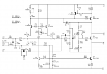
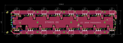
anyway , to cut story short, here is first hand of FE pcb made ditto for OS pcbs posted few days ago
mounting of FE to OS with 2 spacers (holes 3.2mm) , all connecting pads aligned
resisted Babelfishing urge, added one cap and few base/gate resistors
shoot me
few minor important changes from Pa's schm (post #1) - no output signal return from OS to FE, thus protection diodes and Boucherot cell are placed on OS pcb; price is small - separate wire from PSU central GND point must be wired to OS pcb
no SMD parts on FE, even if I started with few ....")
I'll optimize everything in next few days, but simple Yay (or Nay) nod could save my day
be well, stay safe, all
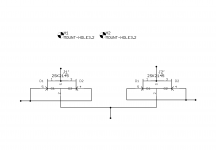
edit: oh yes - didn't resisted putting bottom footprint for my fave 2SK2145
OK, wasn't that much alleluia moody, but I know Pa have these days some other things to think of, so here it is ....... maybe some work shaven from his pile
(Pa - remember that scene from War Lover book - two old guys moving load of planks from vehicle to ground ...... and bunch of eager young guys did that for them in 10 mins.... )
anyway , to cut story short, here is first hand of FE pcb made ditto for OS pcbs posted few days ago
mounting of FE to OS with 2 spacers (holes 3.2mm) , all connecting pads aligned
resisted Babelfishing urge, added one cap and few base/gate resistors
shoot me
few minor important changes from Pa's schm (post #1) - no output signal return from OS to FE, thus protection diodes and Boucherot cell are placed on OS pcb; price is small - separate wire from PSU central GND point must be wired to OS pcb
no SMD parts on FE, even if I started with few ....
I'll optimize everything in next few days, but simple Yay (or Nay) nod could save my day
be well, stay safe, all
edit: oh yes - didn't resisted putting bottom footprint for my fave 2SK2145
Attachments
Last edited:
Thanks again ZM, you must have been up early this morning there. Nelson has replied to me that 6 to 8mA Idss will be fine here. I do have some tightly matched 2SK170BL in that range, although Nelson also said matching to 1mA will be fine.
I assume the 2 JFets in the SMD package are already matched to some degree by Toshiba?
I assume the 2 JFets in the SMD package are already matched to some degree by Toshiba?
Last edited:
This is very cool.
Yes, of course. (they are on the same die)
I assume the 2 JFets in the SMD package are already matched to some degree by Toshiba?
Yes, of course. (they are on the same die)
.......
I assume the 2 JFets in the SMD package are already matched to some degree by Toshiba?
good enough
and because I'm using them (two) in parallel, effectively as one JFet, matching of two in same case/die is effectively irrelevant
- Home
- Amplifiers
- Pass Labs
- New Stasis front end