This thread is to share some details and reflections of Rawson built amps in need of repair.
I first signed up for DIYAudio when I was trying to fix hum in 2 Rawson Aleph J mini amps built by Rawson. After lots of reading, learning, and coaching I got those amps fixed up. Then I did Rawson repair for a friend on his amps. That lead to some F5 rebuilding, and then fresh builds of other amps here.
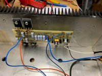
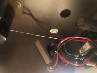
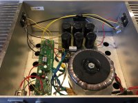
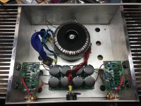
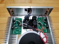
Here is an amp I'll be repairing -
The good:
• Aleph J circuit
• Gain, Bias, Offset measurements are operating to spec, great sound from amp
• Genuine Toshiba JFETs
• IRFP240 Mosfets
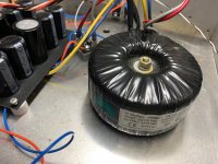
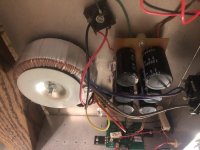
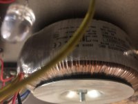
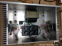
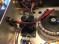
• Plitron 300VA 18+18V Transformer
• Dual Rail / Decoupled Stereo Configuration
The not-so-good:
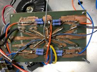
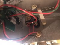
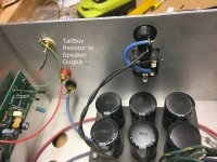
• Grounding: No safety ground on AC Mains, no thermistor
• Poor quality PSU PCB build
• Single Rectifier Bridge / Center Tapped Transformer
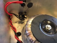
• Loose Power Transformer
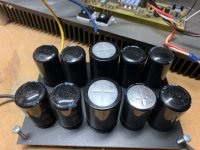
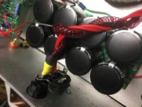
• Bulging PSU caps (about to fail)
• 2nd stage PSU caps rated at 25V (~5% from operating voltage)
• Transformer is buzzing/humming
• No bleeder resistors
• No A/C mains capacitor
• Wiring: orange for +, blue for -, blue for gnd, black lamp cord for speaker -. Blue and orange look great on Gulf livery Porsches, but not in PSU wiring...
• Single thermistor in the AC mains
What will get fixed:
• Add proper grounding
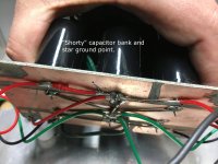
• New Dual Rail Decoupled Stereo PSU board - Jeff Young board
• Use 35V rated capacitors
• Go from center tap config to dual bridge using Schottky rectifiers
• Add power supply snubber circuit
• Add AC Mains Thermistors & 0.0033 A/C Line Cap
• Transformer - suggest swapping to Antek 3218 transformer
• Update aging electrolytic capacitors to Elna Silmic II’s
• Optional - add XLR's
• Proper wire coloring
I first signed up for DIYAudio when I was trying to fix hum in 2 Rawson Aleph J mini amps built by Rawson. After lots of reading, learning, and coaching I got those amps fixed up. Then I did Rawson repair for a friend on his amps. That lead to some F5 rebuilding, and then fresh builds of other amps here.
Here is an amp I'll be repairing -
The good:
• Aleph J circuit
• Gain, Bias, Offset measurements are operating to spec, great sound from amp
• Genuine Toshiba JFETs
• IRFP240 Mosfets
• Plitron 300VA 18+18V Transformer
• Dual Rail / Decoupled Stereo Configuration
The not-so-good:
• Grounding: No safety ground on AC Mains, no thermistor
• Poor quality PSU PCB build
• Single Rectifier Bridge / Center Tapped Transformer
• Loose Power Transformer
• Bulging PSU caps (about to fail)
• 2nd stage PSU caps rated at 25V (~5% from operating voltage)
• Transformer is buzzing/humming
• No bleeder resistors
• No A/C mains capacitor
• Wiring: orange for +, blue for -, blue for gnd, black lamp cord for speaker -. Blue and orange look great on Gulf livery Porsches, but not in PSU wiring...
• Single thermistor in the AC mains
What will get fixed:
• Add proper grounding
• New Dual Rail Decoupled Stereo PSU board - Jeff Young board
• Use 35V rated capacitors
• Go from center tap config to dual bridge using Schottky rectifiers
• Add power supply snubber circuit
• Add AC Mains Thermistors & 0.0033 A/C Line Cap
• Transformer - suggest swapping to Antek 3218 transformer
• Update aging electrolytic capacitors to Elna Silmic II’s
• Optional - add XLR's
• Proper wire coloring
Attachments
Last edited:

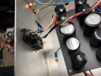
Wow...that PSU is quite something. I have not seen bulging caps like that before.
I wonder if the Plitron will quiet down once you fix everything else. Hopefully
you won't actually have to replace it.
I think you're now a certified Rawson rehabilitation specialist.") Have fun with
Have fun with
the rebuild.
I wonder if the Plitron will quiet down once you fix everything else. Hopefully
you won't actually have to replace it.
I think you're now a certified Rawson rehabilitation specialist.
Have fun withthe rebuild.

This amp remind me of White Van Speakers. White van speaker scam - Wikipedia
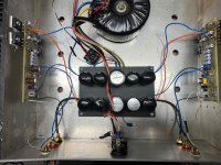
A friend of mine had a Rawson Aleph 4 with way too small heat sinks.
It was %#$@ hot!! What I find interesting is people say they buy the amps from a person who bought it from Rawson, never direct from Rawson.
At any rate, once you have it apart, drill out some extra ventilation.
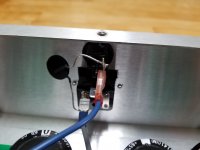
Also the power switch is sensitive to solder iron heat. If the switch doesn't make a satisfying "click" sound or feel solid, the switch was over heated. Doesn't look soldered here, but if you decide to make it a more permamanent connection, beware of too much heat.
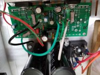
The orientation of the board might not be in the most optimal position.
The mosfets will be heating that specific part of the heat sink before radiating out.
If you have an amp where the mosfets are closer to the bottom, you will find that the warmest places are directly at the top of the heat sink inline with the mosfets, and of course where the mosfets are attached. There maybe cooler spots on the heat sink with all 4 mosfets inline.
Good luck!
A friend of mine had a Rawson Aleph 4 with way too small heat sinks.
It was %#$@ hot!! What I find interesting is people say they buy the amps from a person who bought it from Rawson, never direct from Rawson.
At any rate, once you have it apart, drill out some extra ventilation.
Also the power switch is sensitive to solder iron heat. If the switch doesn't make a satisfying "click" sound or feel solid, the switch was over heated. Doesn't look soldered here, but if you decide to make it a more permamanent connection, beware of too much heat.
The orientation of the board might not be in the most optimal position.
The mosfets will be heating that specific part of the heat sink before radiating out.
If you have an amp where the mosfets are closer to the bottom, you will find that the warmest places are directly at the top of the heat sink inline with the mosfets, and of course where the mosfets are attached. There maybe cooler spots on the heat sink with all 4 mosfets inline.
Good luck!
Last edited:
Wow I don’t think I could sleep at night with that power supply, a good starting point to entering diy would be to replace it with the universal power supply sold in the diyaudio shop. Mr Pass always the gentleman if anyone has a right to get his feathers ruffled and instead he just imparts more wisdom .
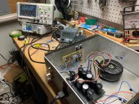
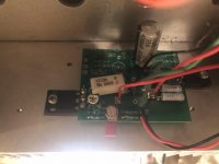
Here are pics of the next one. I don't have it yet. I'll get it after the AJ is done. Any idea what that circuit is?
Attachments
Here are some pix of the first ones I worked on. Before pix.
Attachments
-
 IMG_9664s.JPG505.3 KB · Views: 269
 -
 IMG_9649s.JPG548.3 KB · Views: 321
 -
 IMG_9659s.JPG421.7 KB · Views: 324
 -
 George B1 Aleph J Mono 02.jpg700.7 KB · Views: 250
 -
 John S1 Aleph J Mono 01.jpg729.8 KB · Views: 260
 -
 John S1 Aleph J Mono 04.jpg650.7 KB · Views: 250
 -
 IMG_0154.jpg985.5 KB · Views: 242
 -
 IMG_0156.jpg857.4 KB · Views: 258
Last edited:
Here are pics of the next one. I don't have it yet. I'll get it after the AJ is done. Any idea what that circuit is?
sorta late , so fuzzy to check - see any of first Fx amps - one of them having fat resistor across output
can't see - is there LU hidden somewhere?
funny - pcb looks as for some other amp initially, cut abruptly
I think it’s a zen from “zen variations 2” with the Aleph CCS.
See figure 6-
Zen Variations 2 | Pass DIY
Yes, PCB appears chopped.
See figure 6-
Zen Variations 2 | Pass DIY
Yes, PCB appears chopped.
I think it’s a zen from “zen variations 2” with the Aleph CCS.
See figure 6-
Zen Variations 2 | Pass DIY
Yes, PCB appears chopped.
good eye ....... and memory
but, you're Youngster
I was just getting started on diy and ended up with a rawson amp - did not know about the history and issues with these. I hope to watch and at least make it safe!
Crack it open and share some pix. I’m happy to give some tips, and I’m sure others are, too.
When I get parts in I’ll update the amp in post #1 and share the “after” pix.
Interior view
Crack it open and share some pix. I’m happy to give some tips, and I’m sure others are, too.
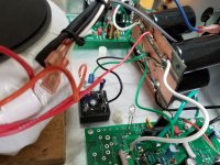
Hi. My first picture upload! Now that I look inside, it is not good. Seems to be no ground and pcbs floating in space...
Crack it open and share some pix. I’m happy to give some tips, and I’m sure others are, too.
Hi. My first picture upload! Now that I look inside, it is not good. Seems to be no ground and pcbs floating in space...
Attachments
Hi. My first picture upload! Now that I look inside, it is not good. Seems to be no ground and pcbs floating in space...
You have a ground issue indeed. Can you send a few more pix zoomed out? I've never seen the half height heatsinks. Also, that appears to be a massive donut. What boards are those? Or more to the point, what circuit it it? Based on the size of that donut there looks to be little to no room to put a different PSU PCB in there. Can you also get a picture or two with the cover on?
- Home
- Amplifiers
- Pass Labs
- Rawson Repair Reflections