I forgot to mention mine arrived last Tuesday. Thank you 2pico and Gianluca.
Oh yeah

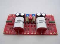
Made a bit of progress. Long time coming. Two sets of BA-2 output boards and bias boards. I've had the "6 per side" BA3 running for quite some time and love it. I had the extra boards and a pile of matched output devices from the original build saved in "categories" for future use. I wanted to save enough to do the "full amp" to add later and not accidentally use them in a different project.
I took apart the old amp, added the additional output devices, and we'll get it back going maybe next weekend. Waiting on a few bits from Sonic Craft and a few other parts. I maaaaaaaay go the balanced monoblock route later, but for now it will be a dual mono stereo amp. I need to work out whether I'll use a switching solution for balanced / SE or just leave it hard-wired one way or the other.
I think what I'm going to do is build the BA-1 single ended output boards and try that with the BA-3 front end and compare side by side. Then I can decide which route to take after that.
Enough rambling, this is the chassis thread...
Not full on porn, but a bit of a tease....
Attachments
![63621815347__E6D741CD-2211-4928-AF79-13F8FC52CCA3[5394].jpg](/community/data/attachments/832/832176-1cc57b1d0f1e9336bfa6868d86ddc0dd.jpg)


Ozorfis - Thanks! Look for a PM. I think I have the switch sorted, but I don't think I've ever been so paranoid. Plus, I don't really want to order "mini-PCBs" for the DIP switch, so...
ZM - A guy's gotta do, what a guy's gotta do. No purpose other than to learn, and b/c I can. I admit it hurt a bit to take apart the other amp, but...
HeyBill -
I gotta admit, just looking at them makes me smile. That's enough for now to keep me going.
Edited to add - AlexRivera - you can put 24 with no extra tapping ... depending on the layout of the PCB.
ZM - A guy's gotta do, what a guy's gotta do.
No purpose other than to learn, and b/c I can. I admit it hurt a bit to take apart the other amp, but... HeyBill -
I gotta admit, just looking at them makes me smile. That's enough for now to keep me going.
Edited to add - AlexRivera - you can put 24 with no extra tapping ... depending on the layout of the PCB.
Last edited:
AlexRivera - you can put 24 with no extra tapping ... depending on the layout of the PCB.
You are right, it’s just a matter of using an aluminum bar across the transistors to fix the ones without a screw, that may work for Class A/B, for pure Class A 12 pairs may me more that what the heathsink can dissipate, isn’t it?
You are right, it’s just a matter of using an aluminum bar across the transistors to fix the ones without a screw, that may work for Class A/B, for pure Class A 12 pairs may me more that what the heathsink can dissipate, isn’t it?
Sorry for poor description. I was talking about just in theory vs. amps I know of that can take advantage of it.
If someone designed an amp with a set of PCBs that had 12 devices on the "upper" side of the board and 12 on the "lower" side of the board, they'd fit in like a treat with the UMS. There's 12 "unused holes" in mine. Think F5 Turbo layout with MOSFETs up and down. Otherwise, I've seen creative builders have their PCBs perpendicular to the heatsinks and "back to back" for BA builds. Itsmee should get credit for passing that idea along to me when I was going to do this in a 5U/400. Now that I have this chassis, there is no need.
Your second piece is the "real" piece that probably matters most. Heat. It would depend on the amp, the devices used, and the bias. A BA-3 with 24 devices, even with my "low" 24V rails and biased to 0A75 per device would still be 432W to dissipate. I biased my "6 device" BA-3 to 1A0 per device in the 5U/400 just to test it out, and thermals were okay. So, I feel pretty good that getting to 0A5 with 12 per side with these sinks should be fine.
Someone should check my math though... not my strongest suit.
Last edited:
Just in case you change your mind. Attached is the solution of somebody else, that I found on this forum. I will do something similiar with my toshiba versions. I resoldered the gnd connection a couple of times already and one time I might end up burning my caps like 6L6 did. Good luck and best of wishes
Ozo
Ozorfis - Thanks! Look for a PM. I think I have the switch sorted, but I don't think I've ever been so paranoid. Plus, I don't really want to order "mini-PCBs" for the DIP switch, so...
ZM - A guy's gotta do, what a guy's gotta do.
HeyBill -
I gotta admit, just looking at them makes me smile. That's enough for now to keep me going.
Edited to add - AlexRivera - you can put 24 with no extra tapping ... depending on the layout of the PCB.
Attachments
- Home
- Amplifiers
- Pass Labs
- Ultimate 4U 500mm Chassis - Who is interested?