That does clear things up...
I think sure.... You get the buffer and volume adjust, dc voltage gets stripped off in the end, nothing jumps out as alarming.
The circuit is still attached and powered up with no input attached.Not sure if that would be a factor in any way. Ehhh.
Test rig it...
As always I defer to the greater minds here. If we are overlooking anything hopefully they will step in. In other words , wait for some consensus , but your thinking seems sound to me.
Good luck with it....fun to see if it works out.
Check with an ohmmeter to see if your supply ground is attached to AC earth ground,
and through how many devices. You would want to check each component individually
without being attached to the rest of the system. When multiple components share
ground with the AC then you have the potential for ground loops and you can then use
a "cheater" adapter to break individual AC ground connections and see if it fixes
the noise.
Do you recommend a CL-60 between supply ground and AC earth ground?
All depends on your level of trust. Best isolation + safety would be chassis with hard AC earth ground with power thermistor in parallel with power diodes (you can use rectifier bridge) to your circuit ground.
Your isolated medical grade desktop switcher would be presumed pretty safe...
I have a Meanwell medical grade SMPS for the power supply. I'm building a BA2018 line stage with the 6-24 crossover together in one chassis, and a separate chassis for the power supply. I've reread your article on the crossover and understand the power supply should "float", it's the mains wiring I want to get correct.
I've used the rectifier bridge ground circuit on amplifiers, I wasn't sure about line stages. The Meanwell supply has a mains ground connection along with hot and neutral. I'm using Mark Johnson's VRDN supply for the BA2018, I'll use the rectifier bridge for it and try chassis ground direct to the Meanwell ground point.
If I get problems, I can move it to the rectifier bridge.
The biggest ground loop issues seem to generally be between components in different chassis rather than different circuits in the same chassis, although this could be an issue. In the case of the Meanwells issues are much more likely to occur when the circuit ground is directly connected to AC Earth.
Thanks for that information. I'll be sure to use a rectifier and thermistor for each power supply to earth ground.
I was planning on the line stage, crossover, muse volume control and the Salas iselect all floating with no connection to chassis ground in the other enclosure.
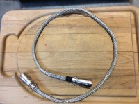
The umbilical between enclosures will have a braided shield over all the wires with the shield electrically connected to the power supply chassis only..
I was planning on the line stage, crossover, muse volume control and the Salas iselect all floating with no connection to chassis ground in the other enclosure.
The umbilical between enclosures will have a braided shield over all the wires with the shield electrically connected to the power supply chassis only..
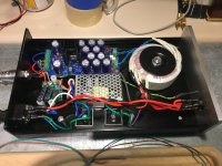
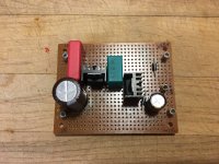
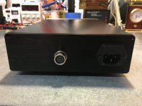
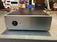
Finished my power supply for an integrated preamp using the BA2018 line stage and 6-24 crossover. The 6-24 crossover uses a Meanwell medical grade 24v SMPS, I have two of Mark Johnson's SMPS filters, one in the remote power supply case and the other in the integrated enclosure. The Meanwell SMPS has an adjustable output voltage so I was able to dial in 24v after the two filters.
The other supply is a VRDN set to +- 18vdc, which will feed the BA2018 line stage. I'm using a Salas In-select and an Academy Audio VCU muse volume control. Since they both operate at +- 15 vdc, I built a dual rail 15v regulator to drop the +- 18 vdc to +-15 vdc. Mark Johnson posted the basic schematic for the 7915 and 7815 regulators, the data sheet had all the info on values of the components based on location of the regulator and type of capacitors used. First breadboard circuit I've built in several lifetimes.
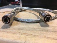
The umbilical cord uses 5 pin Tajimi quick connect connectors, my Threshold FET10 Pe uses a 3 pin connector for the raw power supply. I really like these connectors so I bought the 5 pin female chassis and male inline connectors.
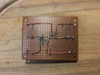
How do I test the 6-24 crossover PCB? I have the LED on, however, I do not know how to test the circuit before I install it into the enclosure.
The other supply is a VRDN set to +- 18vdc, which will feed the BA2018 line stage. I'm using a Salas In-select and an Academy Audio VCU muse volume control. Since they both operate at +- 15 vdc, I built a dual rail 15v regulator to drop the +- 18 vdc to +-15 vdc. Mark Johnson posted the basic schematic for the 7915 and 7815 regulators, the data sheet had all the info on values of the components based on location of the regulator and type of capacitors used. First breadboard circuit I've built in several lifetimes.
The umbilical cord uses 5 pin Tajimi quick connect connectors, my Threshold FET10 Pe uses a 3 pin connector for the raw power supply. I really like these connectors so I bought the 5 pin female chassis and male inline connectors.
How do I test the 6-24 crossover PCB? I have the LED on, however, I do not know how to test the circuit before I install it into the enclosure.
Attachments
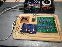
Hello elwood625,
very nice work!
I have tested my 6-24 crossover by using a sine wave generator. Output set to 0,5V. This signal goes to the 'input' of the 6-24.
Test the 'lowpass- output':
(my crossover-frequency is at 2500Hz)
step1: I started with a sinewave of 1000Hz at 0,5V - at the output you should measure a sinewave with a voltage swing
very close to 0,5V (it will be a little below 0,5V - anywhere around 0,48V - it is a buffer with some very slight damping)
step2: next sinewave at 2000 Hz - output-measurement should become lower (let's assume anywhere around 0,45V)
step3: next sinewave at 2500 Hz (the chosen crossover frequency) - depending on the chosen slope (6dB /12dB/18dB/24dB)
your measured voltage swing at the output will go down (as higher the slope - as faster).
step4: sinewave of 5000 Hz at the input of the 6-24 (one octave above the crossoverfrequency) - voltage swing of sinewave at output/lowpass
should be damped by 6dB/12db/18db/24dB - depending on the chosen slope.
Test the 'highpass-output':
at the input same signal as above = 1000 Hz / 0,5 V - you should measure only a very low outputsignal
then you go up with the frequency of your sinewavesignal
as closer you get to your chosen crossoverfrequency - the voltageswing should go up = closer to 0,5 V.
I hope this helps? Have fun - it is an excellent active crossover!
Cheers
Dirk")
very nice work!
I have tested my 6-24 crossover by using a sine wave generator. Output set to 0,5V. This signal goes to the 'input' of the 6-24.
Test the 'lowpass- output':
(my crossover-frequency is at 2500Hz)
step1: I started with a sinewave of 1000Hz at 0,5V - at the output you should measure a sinewave with a voltage swing
very close to 0,5V (it will be a little below 0,5V - anywhere around 0,48V - it is a buffer with some very slight damping)
step2: next sinewave at 2000 Hz - output-measurement should become lower (let's assume anywhere around 0,45V)
step3: next sinewave at 2500 Hz (the chosen crossover frequency) - depending on the chosen slope (6dB /12dB/18dB/24dB)
your measured voltage swing at the output will go down (as higher the slope - as faster).
step4: sinewave of 5000 Hz at the input of the 6-24 (one octave above the crossoverfrequency) - voltage swing of sinewave at output/lowpass
should be damped by 6dB/12db/18db/24dB - depending on the chosen slope.
Test the 'highpass-output':
at the input same signal as above = 1000 Hz / 0,5 V - you should measure only a very low outputsignal
then you go up with the frequency of your sinewavesignal
as closer you get to your chosen crossoverfrequency - the voltageswing should go up = closer to 0,5 V.
I hope this helps?
Have fun - it is an excellent active crossover!Cheers
Dirk
Hello Kang Kel,
the DIYAudioStore - case originally made for the 6-24-active-crossover is no more available for a pretty long time.
I think you should make one on your own. Buy a universal modushop case with the size, that 2 pcbs fit side by side.
If you want to make a 'doubledecker' - also possible. But you should have access to your potentiometers on the boards
and you will have to flip your caps of the CRC-filter to the side / 90 degrees.
I would go side-by-side...
Cheers
Dirk
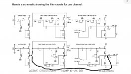
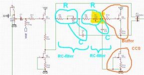
Past few days were perfect to sit down and fiddle with EasyEDA. When placing parts on the virtual pcb, I stumbled on the "wipers" of both P1's of the low pass filter.
Should it not point to the cap (C/2) instead of the 10k resistor preceding it? Do tell me if I am going crazy, I have been at it for a while and might not see it anymore


Should it not point to the cap (C/2) instead of the 10k resistor preceding it? Do tell me if I am going crazy, I have been at it for a while and might not see it anymore
- Home
- Amplifiers
- Pass Labs
- DIY biamp 6-24 crossover