Question for Nelson.
Is there any reason not to try jFets without bias resistors as you did in the B1 buffer?
I have some jFet pairs that have a lower Idss than the provided j113s but are within .05mA of each other. To bias them down 10% needs only single digit Ohm resistor and doesn't really change the dc relationship to the surrounding circuitry, so I'm wondering why bother.
After reading your description in the B1 manual and how much you enjoyed the sound it seems worthwhile asking about.
Thanks
") )
) )
)Do check your freq responses; even though I used the XO Calculator, I found my R values weren't giving me the expected XO freq. Still a great & appreciated resource, but proof is in the measurements & the listening!
FYI: 12dB 6k XO should have worked with 2200pF caps & R 12k, but got me in reality an XO ~4kHz. Reduced R to 10k, better. Still measuring/listening. May try 1500pF or 1000pF caps to see if any difference (did buy a selection of different values in board-sets just to try, & 6 boards).
500Hz XO for bass/midrange fine, it's just the mid-treble integration....
Am using a DC-protect cap on tweets, maybe they affect it, dunno, don't particularly care, all sounds pretty good.
Still in Covid lockdown, can't go more than 5km from home for at least another 3 weeks.
Just as well I have Diyaudio & music (& beer & wine).
Last edited:
Is there any reason not to try jFets without bias resistors as you did in the B1 buffer?
No reason. You can run the fets at Idss with quite small thd penalty.
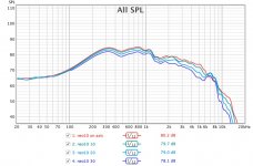
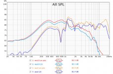
I thought I needed 2 boards for what I needed to do for a pair of speakers. Now, I see, I needed 2 boards per speaker! However having the second board just to have 200hz high-pass seems excessive. The drivers are in horns and have a natural roll-off at 200hz, so it is more protection. Here are the measurements I did with minidsp. A pair of BG neo 10's (bw12 at 100hz and lr12 at 4800hz, no eq) a single modified neo3 (lr12 at 200hz, no eq)
I attach neo 10 on axis and 10, 20, 30 off axis measurements. I also attach neo10 and neo3 drivers superimposed on top of each other. On axis and 20 degrees off axis
Maybe there is an easier way to add a 200hz high-pass for my intended purpose.
I attach neo 10 on axis and 10, 20, 30 off axis measurements. I also attach neo10 and neo3 drivers superimposed on top of each other. On axis and 20 degrees off axis
Maybe there is an easier way to add a 200hz high-pass for my intended purpose.
Attachments
What a difference a coupling capacitor makes
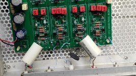
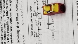
I used a mystery 4.7uf output coupling capacitor on the hi-pass and it sounded rather bright for my taste. Today I removed the cap and bypassed it with a piece
Scrap wire, and lifted the 47K resistor . From the output pad on the board I placed a 1Uf MIT multicap to the output jack. Then I placed a 47K resistor across the jack. It made huge difference in sound, gone are those steely bright highs. I am loving the sound. The crossover point is set for 200 HZ so the low frequency roll off set by the output cap and the load is no problem.
Attachments
No reason. You can run the fets at Idss with quite small thd penalty.
Thanks ! Done and in place. Not sure I could ever distinguish the difference in thd, but I like the sound.
Roger is right.
BTW you could split in left and right to have monophonic crossover boxes.
That is my aim. I have bought two boards to make monophonoic crossover boxes. I need -for each speaker- one band pass and one hi-pass filter. For example, a 180hz-1600hz bandpass filter and 1600hz hi-pass filter.
I can solder nicely and have already builded several speakers physically including this one but I am not versed in electronics at all, I aşways had someone else build the crossovers, hence my questions.
I am going to complete the crossovers this weekend as I have received all the parts. I am just not putting any resistors down in c and c/2 yet, as I need to understand better. I will share my crossover build.
Preface: my proto boards are built & working, LR2 XOs@500Hz & (close to) 6kO.
Music sweet, but trimpots need to go (drift with temp/vibration)!
Next iteration is to replace trimpots with fixed Rs & match components as needed.
If there is a build guide that helps me, please feel free to direct me to it. Otherwise:
Some questions for Nelson (or suitably-knowledgeable apprentices):
1. The 6-24XO doco suggests we want the jfets to use "8mA current in the buffers".
Is that ~800mV across bias resistor for each jfet?
My supply is 20-21VDC after RC filtering. Does the actual measured value matter (in the scheme of things)?
2. Am I correct to match L-chan & R-chan Q1 & Q2 bias to each other, so gotta match in quads, or L/R/Q1/Q2/Lowpass/Hipass, so octets?
3. To what extent is matching jfets important? If so, to what tolerance (1/5/10%)?
4. If I eventually want to use this XO with balanced source &/or amps, do I "double-up" boards (& match very carefully), or just use a bal/unbal input & one or more unbal/bal outputs to my amps?
5. If I go balanced all the way through, how do I do power supply?
6. For balanced equipment use, is LX-mini the "better" (more appropriate) choice?
Supplied jfets are a mix of 3 or 4 manufacturing plants & date codes.
I surmise if they measure the same, it doesn't matter where or when they were made?
All bias Rs were nominally 100O, bulk supply, so no particular marching of Rs.
Other resistors are 1%, caps are 2.5% & matched better to the limits of my kit LCR meter, but matching fets is new to me.
Thanks...
Last edited:

Preface: my proto boards are built & working, LR2 XOs@500Hz & (close to) 6kO.
Music sweet, but trimpots need to go (drift with temp/vibration)!
Next iteration is to replace trimpots with fixed Rs & match components as needed.
If there is a build guide that helps me, please feel free to direct me to it. Otherwise:
Some questions for Nelson (or suitably-knowledgeable apprentices):
1. The 6-24XO doco suggests we want the jfets to use "8mA current in the buffers".
Is that ~800mV across bias resistor for each jfet?
My supply is 20-21VDC after RC filtering. Does the actual measured value matter (in the scheme of things)?
2. Am I correct to match L-chan & R-chan Q1 & Q2 bias to each other, so gotta match in quads, or L/R/Q1/Q2/Lowpass/Hipass, so octets?
3. To what extent is matching jfets important? If so, to what tolerance (1/5/10%)?
4. If I eventually want to use this XO with balanced source &/or amps, do I "double-up" boards (& match very carefully), or just use a bal/unbal input & one or more unbal/bal outputs to my amps?
5. If I go balanced all the way through, how do I do power supply?
6. For balanced equipment use, is LX-mini the "better" (more appropriate) choice?
Supplied jfets are a mix of 3 or 4 manufacturing plants & date codes.
I surmise if they measure the same, it doesn't matter where or when they were made?
All bias Rs were nominally 100O, bulk supply, so no particular marching of Rs.
Other resistors are 1%, caps are 2.5% & matched better to the limits of my kit LCR meter, but matching fets is new to me.
Thanks...
Try 25 K single gang linear pots.
If you bought the kit L+R jfet matching is unnecessary.
L+R level matching of low and high output is more critical. Use REW software and match the levels at 1 metre as closely as possibly for L&R with a Minidsp calibrated microphone.
Check the phase tracking of the woofer and tweeter by reversing the phase of the drivers. A dip of 20-25 dB should appear within one octave pink noise at the crossover point if the a acoustic phase relationship is correct between the drivers.
I recommend you first try unbalanced. There is no real improvement in attempting a full balanced signal in consumer audio unless you have very long cables. It’s BS unless your amp requires a balanced input. The SE signal is often less noise and lower distortion due to the absence of the differential input and sub optimal impedance matching. For good CMRR the impedance needs to be matched to less than 1% which is rare in practice with HIFi as they are rarely 600R balanced lines. If you must Do balance use input opamp like the mo amps discrete opamp with a differential input mH and a phase inverter on the outputs.
On the question of PS l would use a separate smps on each board.
Depending of the way your preamp rca or XLR wiring is set up you may or may not encounter earth loops. Do not lift the power amp or preamp chassis earth with a jumper ac this is a danger in the event of a fault.
A 10R resister in series with the shield of each unbalanced shield can help minimise earth loops.
It’s not a matter of having a clearly defined process for setting up the crossover with your loudspeaker system. Unless your drivers have at least one octave flat linear response either side of the crossover point you will need to do sone trial and error to get the correct acoustic crossover slopes and transformation.
And we have music! Quite good right from the start. I thought that bass was a bit shy in lower regions.. But then I dialed up the low pass which solves it for the moment. I currently have 1.5nf on left and right side C's (the ones part of the psu). Is this ok?
Next up is removing x over from LS too hear the "real" result crossing at 4k, and of course measuring[emoji6]
As my day flew by enjoying this, I will have to get out of my rabbit hole and spend some time with the girlfriend...


Next up is removing x over from LS too hear the "real" result crossing at 4k, and of course measuring[emoji6]
As my day flew by enjoying this, I will have to get out of my rabbit hole and spend some time with the girlfriend...
- Home
- Amplifiers
- Pass Labs
- DIY biamp 6-24 crossover