NPass-schematic_24dB -MRcalc in red
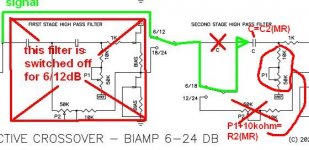
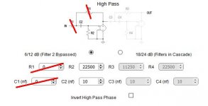
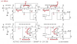
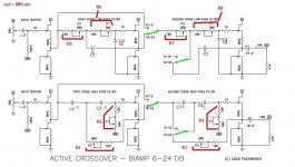
I tried to put in the MRcalculator Rs and Cs (in red) into the schematic of Nelson Pass (24dB-slope).
I hope I made no mistake!
You can throw old vegetables and fruits on me, if.....
Greets
Dirk
I am a bit nervous - how you respond...
I tried to put in the MRcalculator Rs and Cs (in red) into the schematic of Nelson Pass (24dB-slope).
I hope I made no mistake!
You can throw old vegetables and fruits on me, if.....
Greets
Dirk
I am a bit nervous - how you respond...
Attachments
So I think you have it, R1 = P1 and R3 = P1 and so on
Apparently I can't edit my post #659 but the last part should read:
R2 = P1, R3 = P1 ... as cubicincher helpfully shows
To: cubicincher
Quick question. Your first build looks to have Hp, Lp, level pots for each channel. Did you find that you had to set them appreciatively different per channel, or could one use two gang/deck pots without to much deviation?
Also thanks fro your previous advice on the psu, i'm still working out what I'm going to use.
Regards
Tbone
to TboneAK #665
Hello TboneAK,
if you go active, you drive each loudspeakerchassis with its own ampchannel.
You will need more power to drive the woofers than driving a mid/tweeter.
You perhaps have different powerful amplifiers for low and high frequencies.
You will need adjustability (potentiometer) for the high pass and low pass.
Especially if you want to experiment with different amps and speakers.
You could use a double gang pot for left and right lowpass
and one double gang pot for left and right highpass. That would make sense to me. Hopefully the double gang pots have some accuracy between the two channels.
Many stereo-pots have inaccuracy up to 20% between the two channels. This is why I prefer single channel / precision 10 turn pots. But it is not necessary.
Greets
Dirk
Hello Dirk,
So the take away here is, I'm unlikely to get matching output levels at my speakers using stereo pots. Having fine tuning ability for each H/L pass filter and channel is the goal.
-I have two 2ch amps for this project, a F5T 50wpc, and a F6 25wpc. A M2X will be built at some point.
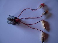
-My plan was to have a stereo pot for each amp. I will be using flying leads for the RCA connectors so I could wire directly to the pots and then to the input pads. I could then use a 1K to 2K5 trimmer on the the boards in place of the 50K trimmers for initial set-up fine tuning. Or I guess just leave the 50K pots on there.
-Because I have early teen-aged kinder in the house, I was considering using these:
https://www.mouser.com/ProductDetail/Alps-Alpine/RK097122TZ0A/?qs=YMSFtX0bdJB9fHMgys1JOw==
-Yes I could just build it as NP designed, but wheres the fun in that?
Best Regards,
Tbone
to TboneAK
Good Morning TboneAK,
now I understand. F5T for lower frequencies / F6 for high pass - nice!
Pots outside ( I also did this a few times with Preamps...).
Teenage kids: Dad, what is that round thingie for? Can I turn it....
And: I am still a bit of teenage in my brain - my body no more!
Cheers
Dirk
Good Morning TboneAK,
now I understand. F5T for lower frequencies / F6 for high pass - nice!
Pots outside ( I also did this a few times with Preamps...).
Teenage kids: Dad, what is that round thingie for? Can I turn it....
And: I am still a bit of teenage in my brain - my body no more!
Cheers
Dirk
Attachments
to cubicincher
Hi Dirk,
Thanks for the feed back. Ya with the kids, the more knobs the more opportunity for them to make "adjustments". It's not like when they were younger and just don't know better. My oldest (13), thinks he's smarter than me half the time. I can hear it now "You said that was the Volume knob", "Which one make more bass?" etc. 
Kids are great, really, but they just have that growing up thing to do.
I think that I'll use those push lock pots mounted in a Hifi2000 chassis with a 10mm front panel. It will be a good deterrent, and look pretty sharp too.
I know that there are better quality pots out there, but for the price and utility I'll give those a go for now.
I think my use of flying leads wasn't correct. The I/O RCA's will be mounted directly to the back panel and connected via wire not to the board. But I like your idea in that pic, that would come in handy for experimenting with different amp combo's.
Best regards
Tbone
Hi Dirk,
Thanks for the feed back.
Ya with the kids, the more knobs the more opportunity for them to make "adjustments". It's not like when they were younger and just don't know better. My oldest (13), thinks he's smarter than me half the time. I can hear it now "You said that was the Volume knob", "Which one make more bass?" etc. Kids are great, really, but they just have that growing up thing to do.
I think that I'll use those push lock pots mounted in a Hifi2000 chassis with a 10mm front panel. It will be a good deterrent, and look pretty sharp too.
I know that there are better quality pots out there, but for the price and utility I'll give those a go for now.
I think my use of flying leads wasn't correct. The I/O RCA's will be mounted directly to the back panel and connected via wire not to the board. But I like your idea in that pic, that would come in handy for experimenting with different amp combo's.
Best regards
Tbone
Need a Yuk?...I'm buying... Have one on me.
Somewhere around 1:15 AM and I was congratulating myself on quitting for the night… “A mans got to know his limitations”… Clint*
Everything was really right … I still get a kick out of gleefully watching the solder wick its way down the lead wire and into the board … “Goldilocks joint’s” just right nice and shinny.
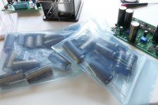
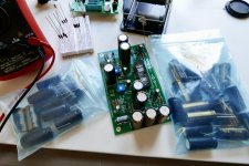
Only major thing left was to solder in the large caps in the morn and test. Board, #4, was for a skeptic nonbeliever, close friend and upscale $$$ audio store owner so anyways chose decent well proven parts. Interestingly the Nichicon UKZ Premium caps do fit…if barely. Need to adjust the lead space a bit etc. but doable.
Awoke, always nice at my age, got properly caffeinated grabbed the bag off the desk and installed them, all eight of them. Went to put the board away and noticed another bag of caps? … the right ones! 1000UF/25’s…not 470UF/50’s. Wife unit noticed I was pretty quiet for the remainder of the day?
Somewhere around 1:15 AM and I was congratulating myself on quitting for the night… “A mans got to know his limitations”… Clint*
Everything was really right … I still get a kick out of gleefully watching the solder wick its way down the lead wire and into the board … “Goldilocks joint’s” just right nice and shinny.
Only major thing left was to solder in the large caps in the morn and test. Board, #4, was for a skeptic nonbeliever, close friend and upscale $$$ audio store owner so anyways chose decent well proven parts. Interestingly the Nichicon UKZ Premium caps do fit…if barely. Need to adjust the lead space a bit etc. but doable.
Awoke, always nice at my age, got properly caffeinated grabbed the bag off the desk and installed them, all eight of them. Went to put the board away and noticed another bag of caps? … the right ones! 1000UF/25’s…not 470UF/50’s. Wife unit noticed I was pretty quiet for the remainder of the day?
Attachments

Hello folks
Been reading your guide on the ACN project. I would like to build a balanced crossover network for a 2 way open baffle project. Full range OB 12" driven by Aleph J and a 15" woofer driven by a class D amp - quite simple and effective.
From reading Papa Nelson post he mentioned that 2 boards would be required for L/R fully balanced signal. My rig is fully balanced in to out. Do you have the wiring diagrams for the XLR balanced crossover network? From what I understand from Papa's post, I would need to build:
XLR input from preamp +/-pins to Left and Right inputs on the board + ground
Left output LOW to XLR1 pin -
Right output LOW to XLR1 pin +
Left output HIGH to XLR2 pin -
Right output HIGH to XLR 2 pin +
and repeat for other board??
What is the 3rd XLR out included in the kit? mids? perhaps be smart to order a chassis large enough for future crossover expansion assuming a 3rd board would be required if I wanted to drive a tweeter in the future
Attachments
to Sebtdi #674
Hello Sebtdi,
you have chosen a challenging project! But sometimes we need challenges in our life....
And you know, that you are in the 6-24XO-thread - not the ACN-thread?
What you describe should work.
You use one ACN-board for a two-way / balanced crossover setup (one channel!)
You feed your balanced signal into the ACN-board:
from XLR - positive signal to input right/ACN
negative (inverted) signal to input left /ACN
output low (right ch) to hot pin XLR (+)
output low (left ch) to inverted pin XLR (-)
ground XLR ground XLR
output high (right ch) to hot pin XLR (+)
output high (left ch) to inverted pin XLR (-)
ground XLR ground XLR
You will have to match your parts from left to right channel carefully.
Or you will get imbalances between positive and inverted signal.
Another difficulty will be the adjustments at the input pots of each filter section. You will have to attenuate the input signal very careful (the same)
for the positive signal and the inverted signal.
And I think you know, that the ACN was designed by Nelson Pass to drive a
Linkwitz-speaker-design.
I think it should/could be possible to adapt this to an open baffle design.
The ACN offers some equalization in the filterdesign (which is necessary in
open baffles).Nelson Pass made the B5 active crossover (no more in production) specially for this. FIRST WATT
And perhaps have a look at this - complicated active crossover....
https://www.magiclx521.com/epages/1...ctPath=/Shops/17940394/Products/"ASP mini NP"
by Nelson Pass.
So I think you will have to 'play' a lot in 'micro-sim' or LTspice to get the values of the parts in the filters 'right'. And I can't tell you if it works and how it sounds with your speakerdesign?!
In my opinion not done in a week....
Also the 6-24XO board will not help you. It has no equalization possibilities
(for bafflestep compensation) in the filters.
Have success!
Dirk
Hello Sebtdi,
So I think you will have to 'play' a lot in 'micro-sim' or LTspice to get the values of the parts in the filters 'right'. And I can't tell you if it works and how it sounds with your speakerdesign?!
In my opinion not done in a week....
Also the 6-24XO board will not help you. It has no equalization possibilities
(for bafflestep compensation) in the filters.
Have success!
Dirk
Dirk - yeah the balanced DIY looks like a long shot. I was thinking of buying a cheap Mini DSP 2X4 to play with the XO values with software until I find them right to my ears with the Open baffles before building the ACN.
Another option is to do the ACN with just one board and short the XLR pins to not use adaptors.
Let me know your thoughts
You will have to match your parts from left to right channel carefully.
Or you will get imbalances between positive and inverted signal.
Another difficulty will be the adjustments at the input pots of each filter section. You will have to attenuate the input signal very careful (the same)
for the positive signal and the inverted signal.
Dirk
I was reading an earlier post from Nelson here that a balanced 2 boards version with 10% match is good enough not to negate noise cancellation of balanced waves..
For the adjustment, I was thinking of using balanced pots front panel mount for Hi/LO for the +/- signals. This way, the gain is the same.
I ordered these attenuators for my build. I’ve used them in the past. They would work well for a balanced build.
Audio Grade 21 steps DACT Type Stepped Attenuator volume knurled Shape Shaft | eBay
Audio Grade 21 steps DACT Type Stepped Attenuator volume knurled Shape Shaft | eBay
6-24XO for subwoofers
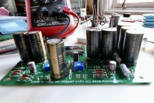
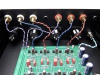
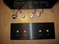
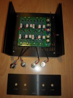
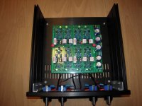
Hello 6-24XO-builders,
today a little progress in my 6-24XO - build for subwoofer:
Got the pcb in the case, LEDs are in contact, volume-pots in the frontplate,....
I have to CAD the backplate and I have to build the PSU. So, still something to do.
Good night from Dirk
Hello 6-24XO-builders,
today a little progress in my 6-24XO - build for subwoofer:
Got the pcb in the case, LEDs are in contact, volume-pots in the frontplate,....
I have to CAD the backplate and I have to build the PSU. So, still something to do.
Good night from Dirk
Attachments
- Home
- Amplifiers
- Pass Labs
- DIY biamp 6-24 crossover