While pursuing Firstwatt's Articles and Mr. Rothacher's threads for years, I've always wanted to build an all SIT amp. I finally started testing one on my workbench, and it seems the amp is working well so far. This amp is similar to Michael's LuminAria + Mofo (L'amp) with some additional ideas.
Feedbacks, critics, ideas and suggestions are very welcome.")
--------
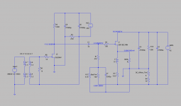
All SIT 50W+ Single Ended Amp (beta)
- All SIT. No other active components sans 2xPSUs.
- Sony 2SJ28 gain + Tokin 2SK182ES follower.
- Minimal signal path. Simple but heavy and hot.
- 600:600 transformer is used for testing.
- Water cooling (will be tested soon).
- Gain: 20dB
- Bias current: Sony 95mA / Tokin 4.2A (updated v1.2)
- Max: 50W+ @8ohm
- Power Consumption: 220W (updated v1.2)
---------------
Updated (V1.2):
Updated Schematics and measurement (V1.2)
Feedbacks, critics, ideas and suggestions are very welcome.
--------
All SIT 50W+ Single Ended Amp (beta)
- All SIT. No other active components sans 2xPSUs.
- Sony 2SJ28 gain + Tokin 2SK182ES follower.
- Minimal signal path. Simple but heavy and hot.
- 600:600 transformer is used for testing.
- Water cooling (will be tested soon).
- Gain: 20dB
- Bias current: Sony 95mA / Tokin 4.2A (updated v1.2)
- Max: 50W+ @8ohm
- Power Consumption: 220W (updated v1.2)
---------------
Updated (V1.2):
Updated Schematics and measurement (V1.2)
Attachments
Last edited:
Measurement
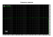
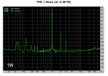
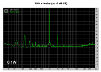
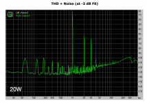
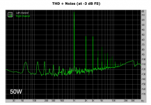
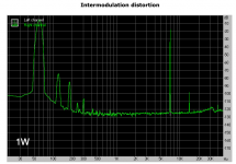
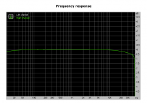
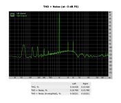
Measurement was done with RMAA @96K. 8ohm dummy load. Looks good to me so far.
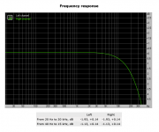
Frequency Response 1W/2.83V -0.21, +0.03
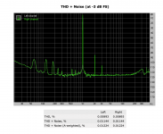
THD 1W/2.83V 0.04147%
THD 0.1W/0.9V 0.02246%
THD 20W/12V 0.28347%
THD 50W/20V 0.46546%
IMD 1W/2.83V 0.04335%
Measurement was done with RMAA @96K. 8ohm dummy load. Looks good to me so far.
Frequency Response 1W/2.83V -0.21, +0.03
THD 1W/2.83V 0.04147%
THD 0.1W/0.9V 0.02246%
THD 20W/12V 0.28347%
THD 50W/20V 0.46546%
IMD 1W/2.83V 0.04335%
Attachments
Last edited:
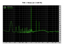
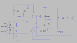
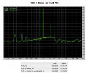
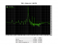
I'm also testing a tranformer-less balanced input version of the amp. The measurement of this version is a little different.
- Same output stage with a long tail pair differential input/gain stage.
- High freq compensation filter (C3) to improve freq response.
- THD @1W/2.83V
- Same output stage with a long tail pair differential input/gain stage.
- High freq compensation filter (C3) to improve freq response.
- THD @1W/2.83V
Attachments
Last edited:
My LTSpice emulations are reasonably close to real amps, thanks to Lynn's 2SK182ES Spice model which is close to my Tokin batch from Watanabe-san (thank you, Lynn & Watanabe-san).
High voltage SONY model below is mine, which was also helpful to predict operational points, but use it at your own risk.
*2SK82 (High Voltage)
*--------------------------------------------------
.SUBCKT 2SK82HV D G S ; Drain Gate Source
+ PARAMS: MU=10.49 X=2.85 K=0.014 N=0.5 VCT=8.57 RG=2MEG
*--------------------------------------------------
B1 D S I=K*PWR(URAMP((V(G,S)+VCT)+(N*LN(V(D,S))+(V(D,S)/MU))),X)
*FOR MULTISIM COMMENT OUT ABOVE LINE (*) AND UNCOMMENT NEXT LINE
*B1 D S I=K*PWR(MAX((V(G,S)+VCT)+(N*LN(V(D,S))+(V(D,S)/MU)),0),X)
R1 G S {RG}
CGS G S 380P
CGD G D 142P
CDS G S 42P
.ENDS 2SK82HV
*--------------------------------------------------
*2SJ28 (High Voltage)
*--------------------------------------------------
.SUBCKT 2SJ28HV D G S ; Drain Gate Source
+ PARAMS: MU=10.49 X=2.85 K=0.014 N=0.5 VCT=8.57 RG=2MEG
*--------------------------------------------------
B1 S D I=K*PWR(URAMP((V(S,G)+VCT)+(N*LN(V(S,D))+(V(S,D)/MU))),X)
*FOR MULTISIM COMMENT OUT ABOVE LINE (*) AND UNCOMMENT NEXT LINE
*B1 S D I=K*PWR(MAX((V(S,G)+VCT)+(N*LN(V(S,D))+(V(S,D)/MU)),0),X)
R1 G S {RG}
CGS G S 380P
CGD G D 142P
CDS G S 42P
.ENDS 2SJ28HV
*--------------------------------------------------
Well, That's it so far.
Thank you, and yes, the measurement is better than my expectation.
The choke for Sony is an old surplus, TF4SX04HA. The values of the parts on actual amp have been changed a little since LTSpice. The topology has not been changed.
Here is the list of the value from actual amp (measured amp).
Amp #1:
- R6 1.3Kohms This transformer termination resistor determines high frequency response.
- L1 0.12L 2x MOT in series (2x 0.06L according to xrk971)
- TrimPods 1K and 10 ohms
- R4 Many small resistors in series, and I don't measure the value.
- J2 Sony VDS 145V / HV 255V - 90mA. I still need to find a sweet spot.
Amp #2 LTP:
- L2 0.1L/2.25A (TF4SX04HA)
- TrimPods 1K and 10 ohms + small resistors
- R6 R9 1K They work fine with my DAC
Temp test result. Now I'm pretty sure that output capacitor can be eliminated, but please do it at your own risk if you want to try it. Inrush voltage is not measured. I will use a speaker DC protection board with delay start anyway.
Temp (Tokin) - Temp (Heatsink) - Speaker terminal DC offset
27C - 27C - -10mV (10 seconds after power on)
40C - 44C - -4mV
40C - 50C - -1mV
*Tokin's top cover is always colder than heatsink.
*The bottom plate of Tokin is about the same temp as heatsink.
*Measured with a heat measurement gun with laser.
I use Arctic MX-4 paste and Alumina sheet from Ebay. Alumina sheet has to be cracked. You can't cut nor make a hole, but works fine with Tokin.
Square ALUMINA CERAMIC TILES / SHEETS - .020" (.5mm) Thick x 4" x 4" - US SELLER | eBay
Last edited:
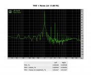
THD comparison of 2SJ28 high voltage gain stage only (Amp#1).
If the goal is lower THD, CCS would be better, but I think I will stick to resistor for now.
*50K ohm load.
*Drain resistor was increased for lower THD.
*2.83V/20V is a little less than 1W/50W amp output.
1 2.83V VDS-150V-90mA drain-1.5K (current configuration)
2 2.83V VDS-150V-90mA drain-0.5K (lower drain resistor)
3 2.83V VDS-90V-70mA drain-0.5K (lower setting)
4 20V @Setting#1
5 20V @Setting#3
6 20V frequency response @Setting#1 (hmm...?)
Attachments
Last edited:
The added drift with this idea might mess with your capless output too much, but since I've been researching/plotting this 2 stage path as well for a while: I'm looking at using a 2sk82 and a choke load to set the follower's bias, negative first PSU like yours too. The Hammond 159S is 65r, 4H, and $25, and your 90mA is almost perfect for -5.6v. 4H seems like enough, you've already tested the 500r that it would give at 20Hz. I don't know how those do at high frequency, etc though.
On that note, the 124D has center tapped outputs that could work on your balanced input stage, maybe. It'd be warming up at 2.5w, 340r per side, they say you can put 5w through it. I don't know, might be fun to try. Too bad the half-nickel 124C is 750r per side.
On that note, the 124D has center tapped outputs that could work on your balanced input stage, maybe. It'd be warming up at 2.5w, 340r per side, they say you can put 5w through it. I don't know, might be fun to try. Too bad the half-nickel 124C is 750r per side.
s610adam, Yes, I wanted to try choke there. Hammond 159S looks good, I put it in my Mouser's cart. Even if doesn't work well, I can use it for PSU choke. 124D is interesting, iron is always welcome@
Capless output is something I have never seen before, and I was also very skeptical about my own idea, but so far, drift seems not to be an issue. Tokin behaves extremely well here. One big question is R10 value.
124D is interesting, iron is always welcome@Capless output is something I have never seen before, and I was also very skeptical about my own idea, but so far, drift seems not to be an issue. Tokin behaves extremely well here. One big question is R10 value.
Last edited:
@woody: the current through L1 and R11 results in about 5.7 VDC, yes...but the output is at about 0 VDC and at the other side of L1-R11 we have minus ~5.8 VDC, so you can ask plasnu for his bank account.
@plasnu: maybe not important but for the sim, two inductances of 0.6H in series is 0.24H instead of 0.12H. In reality though it will not quite reach 0.24H.
How about heat...the 2SK182 dissipates over 100 watts...
@plasnu: maybe not important but for the sim, two inductances of 0.6H in series is 0.24H instead of 0.12H. In reality though it will not quite reach 0.24H.
How about heat...the 2SK182 dissipates over 100 watts...
@daanve, 2 inductors are connected like +-+- (left terminal and right terminal are connected together) and sit next to each other. I wonder if they should be connected like +--+ instead?
It seems that dissipation should be no problem as long as heatsink is big enough. I currently use regular 100W heatsink, and need a fan after 15 min. I was a bit paranoid about heat resistance between heatsink and 2SK182, and I use Alumina, but I'm not sure if it's absolutely necessary. (see post #7) Also we can consider Tokin is a 150C device (Sony is 120C). What you really want to concern is probably room temp.
It seems that dissipation should be no problem as long as heatsink is big enough. I currently use regular 100W heatsink, and need a fan after 15 min. I was a bit paranoid about heat resistance between heatsink and 2SK182, and I use Alumina, but I'm not sure if it's absolutely necessary. (see post #7) Also we can consider Tokin is a 150C device (Sony is 120C). What you really want to concern is probably room temp.
Just thought - you might be getting some meaningful distortion cancellation from using a P channel instead of N on the first stage, based on something from the input buffer of Zen V4, pg2.
"Third, the P channel non-linearity will tend to operate in opposition
to the N channel distortion of the gain Mosfet, giving some
distortion reduction due to cancellation. You can adjust this
cancellation a bit by adjusting the bias current and loading of the
P channel device."
Yeah, the room heat is tough to ignore now that it's summer, but the bias you can put into them is great. I'm trying to make it based on 2 12v batteries to be portable in a truck-camper, and am seriously considering a PC water-cooler loop to an outside radiator
- Status
- This old topic is closed. If you want to reopen this topic, contact a moderator using the "Report Post" button.
- Home
- Amplifiers
- Pass Labs
- All SIT 50W+ Single Ended Amp (beta)