Question re connectors
With respect to the faston connectors between the bridges and the PS, should I use insulated or non-insulated connectors? I thought insulated would be better, but it occurs to me that if I use non-insulated they can also serve as test points. It appears in the guide that both are used (or maybe just non-insulated). Any thoughts on this?
Also what would be a good crimper to get? I have seen these: https://www.amazon.com/dp/B07WMB61J...olid=3ARXUOI2MXALN&psc=1&ref_=lv_ov_lig_dp_it (for insulated connectors); and
https://www.amazon.com/dp/B0006M6Y5...olid=3ARXUOI2MXALN&psc=1&ref_=lv_ov_lig_dp_it (for non-insulated and insulated connectors).
Finally, I would like to have the Aleph J amp board connected to the signal in/out and PS through detachable connectors to facilitate changing boards if I later decide to build another PASS amp. I recall that various members have done this. Someone recommended Molex snap connectors. I think these are they:
19164-0040 Molex | Mouser
https://www.mouser.com/ProductDetai...=/ha2pyFadugBUWf07xjT1vIbvghQQ461i/onb9w1D3I=
Are those the correct ones? Are those all the parts or do I need separate open, closed, or barrel connectors to put inside the housing? Has anybody used the snap connectors?
Would I need a separate pair of crimpers for the Molex snap connectors or could I use the Klein crimpers I referenced above?
I know I am supposed to limit my post to two questions according to ZenMod. But these really are two questions with a couple of subparts. I hope that counts!
Thanks a lot for your help.
Jazzzman
Hi, C9 goes across the transformer primary.
The only connection between the PSU board and the chassis ground should be the ground lift CL60 as shown on the bottom right of the psu schematic.
Andy
Correct. C9 is usually located along with the Cl-60 pair and the primary connections. I put it all on a barrier strip, like 6l6 did in his build guides.
Russellc
I realize this sounds like a stupid question, but I will ask anyway. I just received my two transformers (I am building mono blocks). They are Avel-Lindberg 18-18 volt 250VA. They came in a box, but appear to be wrapped in a plastic covering. I assume I do not remove that covering, or do I? Here are pictures (they keep showing sideways, I tried rotating them but it does not work):
I got a pair of those as well. Excellent quality, really thinking about snagging another pair, but I may make a custom order for what I need. (500VA 18/18).
Right now, in order to test it my M2 is playing wonderfully with only one. It gets pretty warm, but any day I should have the Antek replacement. The A-V transformers are for something else.
Russellc
If you mean a remote First Watt type power supply, no I never built one. I was in on a couple of threads about that. Plan at time was to get 4U size chassis with no heatsinks. Most of my First Watt clones have the exact same transformer and power supply, so I figured strip the transformers and PS boards out of M2 and AlephJ and put them in the 4U sized chassis.
I decided to go mono blocks with the 2 amps I was going to "de-power supply" for the stand alone PS, so never happened.
Russellc
I decided to go mono blocks with the 2 amps I was going to "de-power supply" for the stand alone PS, so never happened.
Russellc
Looking for build tips to facilitate swapping of Pass amp circuits for some additional ideas.
Your choice re: crimpers. Klein are usually nice tools, IMO. Either should work for all the crimps you've listed and more.
I like insulated. I poke around inside a lot, and it gives me some peace of mind.
re: test points - I can't think of a situation where there is not another spot to probe when needed, but I could be mistaken.
The only place I personally use a soldered joint on both ends is the input wiring. I use wee tiny wires, and it just makes me feel better.
Have fun!")
Your choice re: crimpers. Klein are usually nice tools, IMO. Either should work for all the crimps you've listed and more.
I like insulated. I poke around inside a lot, and it gives me some peace of mind.
re: test points - I can't think of a situation where there is not another spot to probe when needed, but I could be mistaken.
The only place I personally use a soldered joint on both ends is the input wiring. I use wee tiny wires, and it just makes me feel better.
Have fun!
Thanks for the response. My plan is to make it easy to substitute the amp boards. That way I will just use the same chassis (with power supply) for a variety of builds.
Oh, I might be thinking of something else. Maybe you saw X's post either in the M2x thread or maybe Wayne's BA2018 linestage thread. Discussion was about quick connects at the power supply to board hookups.
X suggested to take the idea further and showed some nice connectors between board and output devices, making for quick board and output device changes.
Maybe that is what you saw? Pretty sure it was the M2X thread.
Russellc and
@jazzzman I'm tentatively planning to do the same thing, though I'm still probably a year or more out from starting that project.
As Russellc eluded to, xrk971 uses those detachable MOSFET flying lead on a bunch of his recent designs, ALPHA, Alpha Nirvana, ABBB, FH9HVX, as well as some Pass Labs designs as well. He just started offering both sizes of his MOSFET snubber helper boards for sale on their own (separate from any amp boards) to facilitate remote connectorized power transistor mounting on Pass or other designs.
I also saw this https://www.diyaudio.com/forums/pass-labs/166784-pictures-diy-pass-amplifier-527.html#post6264974 fully-loaded preamp that uses a PS in a separate chassis. You could PM him, but it looks like he's using some type of Mil Spec connector for the power umbilical.
Last edited:
Thank you, AllInMyHead, that link is great. It does sound marginally safer to use insulated faston connectors (and that would allow me to use the ratchet crimper which looks like it might be a bit easier to to get a good crimp with).
Russellc, I have been reading all of those threads, so you may very well be correct. I will take another look at them.
Thanks, pinkfloyd4ever, I will take a look at what xrk971 is doing. I am planning on using the DiyAudioStore USM heatsinks, so I will be attaching the amp pcb to the heatsink.
Russellc, I have been reading all of those threads, so you may very well be correct. I will take another look at them.
Thanks, pinkfloyd4ever, I will take a look at what xrk971 is doing. I am planning on using the DiyAudioStore USM heatsinks, so I will be attaching the amp pcb to the heatsink.
Are you planning on using the blade connectors? About 95% of the people who install them don’t use them and attach everything to the terminal blocks.
Well, my goal is to put together a noobs guide, so ideally I'm looking for an approach that is simplest, most reliable, and least likely to confuse (so, in other words, I'm not optimizing for concerns like "easy swapping to different amp boards," etc). So if it can be managed with the terminal blocks, sure!
And thank you again!
Well, my goal is to put together a noobs guide, so ideally I'm looking for an approach that is simplest, most reliable, and least likely to confuse (so, in other words, I'm not optimizing for concerns like "easy swapping to different amp boards," etc). So if it can be managed with the terminal blocks, sure!
OK, on further research, I see @rhing has posted a bunch of good photos in the main illustrated build thread. Based on those, and what he eventually used in his hook up, it looks like these appear to be the complement he used:
1. 4 blade connectors on the input side;
2. 4 euroblock connectors on the output side (altho only 3 are used?); and
3. 2 blade connectors on the output ground (ST_G1, ST_G2).
For the blade connectors, any reason not to just solder wires directly to the pads? Seems simpler and more reliable, assuming you're not intending to disassemble later.
re: connectors, as others have mentioned, I'd also be interested in a design that'd allow me to swap out boards for different amps.
I followed the link above to Rich's build, and noticed there was some discussion about reducing/eliminating hum, by braiding/twisting AC wires, bringing input signal wires as close to the heat sinks as possible, rotating the transformer, or running the ground with the V+ and V- lines. Do you plan to include a bit about that as well in your blog/build guide?
Thanks,
re: connectors, as others have mentioned, I'd also be interested in a design that'd allow me to swap out boards for different amps.
I get that, but the question on my mind is what would most noobs want? I'm worried that poorly crimped connectors might be a significant point of failure, especially for those who have never used a crimper before? I guess if we use connectors with removable insulation sleeves, and insist on soldering along with crimping, that might be the best of both worlds.
I followed the link above to Rich's build, and noticed there was some discussion about reducing/eliminating hum, by braiding/twisting AC wires, bringing input signal wires as close to the heat sinks as possible, rotating the transformer, or running the ground with the V+ and V- lines. Do you plan to include a bit about that as well in your blog/build guide?
I'm trying to keep all of this in mind, and figure out what the "best practice" for wire routing is (if you'd like to take on gathering that from the various posts on the illustrated build guide thread, I'd be grateful!), but in the end some of the final trouble-shooting stuff will likely have to go to the illustrated build guide thread.
My boards are done.
Primaries and secondaries and bridges done.
My terminal barrier and CL-60s and the little blue one cap are done.
Earth ground done.
Back panel done'ish.
Assistance needed:
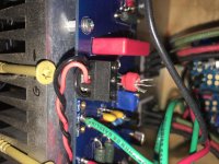
- Trying to figure out what to do with the third CL-60, near the PSU ground, in my 300mm 4U chassis. Which ground? I have almost no room. And what to do with the st_g1 to st_g2? Is it jumpered, too?
- I think the two wires from the IEC connector ("mains," not the switch, which is done) go to the terminal barrier (black, "hot" to the red primary, and white, "neutral" to the black primary), but what wires go to the PSU board on the side closest to the rear panel? I soldered in blade connectors and those screw down Euro connectors bc I wasn't sure which I wanted.
I've been looking at a ton of different completed photos, but it just isn't clear to me or easy to follow.
*Edit: Leaving this here because it's newb type questions this thread needs, but pasting into the build guide thread, too.
Primaries and secondaries and bridges done.
My terminal barrier and CL-60s and the little blue one cap are done.
Earth ground done.
Back panel done'ish.
Assistance needed:
- Trying to figure out what to do with the third CL-60, near the PSU ground, in my 300mm 4U chassis. Which ground? I have almost no room. And what to do with the st_g1 to st_g2? Is it jumpered, too?
- I think the two wires from the IEC connector ("mains," not the switch, which is done) go to the terminal barrier (black, "hot" to the red primary, and white, "neutral" to the black primary), but what wires go to the PSU board on the side closest to the rear panel? I soldered in blade connectors and those screw down Euro connectors bc I wasn't sure which I wanted.
I've been looking at a ton of different completed photos, but it just isn't clear to me or easy to follow.
*Edit: Leaving this here because it's newb type questions this thread needs, but pasting into the build guide thread, too.
Congrats on the progress!
I would encourage taking a look at the schematic for wiring the mains through to the PSU. It is critically important to do it properly. Are you in a 120VAC country?
One of the things that benefits everyone is when asking a question to do the following:
Post or link to the EXACT schematic you are using including any modifications you have made.
Post well-lit, in focus pictures when needed.
The CL-60 you mention goes between the PSU GND and your chassis. On the chassis side of the connection, it ideally should connect directly at the point that your safety earth meets the chassis. Just use the same bolt / connection. Be sure to heatshrink the legs of the CL-60.
When you say "closest to the rear panel" - we can't see how you've configured your design. However, if it's the side with the terminal blocks. Nothing will connect there at this point except your CL-60 to a GND point. That's your "DC output" side. Those are your V+ and V- along with GND connections. You are currently working on getting your mains through PSU working and tested. Nothing else will connect there until you test your PSU.
- Home
- Amplifiers
- Pass Labs
- Aleph J build guide for noobs