You can get matched 2sj74 here:
Toshiba 2SJ74 LAB MATCHED QUAD to 0.03mA / 4mV ("B" "BL" 7-9mA Range) | eBay
Toshiba 2SJ74 LAB MATCHED QUAD to 0.03mA / 4mV ("B" "BL" 7-9mA Range) | eBay
These are genuine -
Toshiba 2SJ74 LAB MATCHED QUAD to 0.03mA / 4mV ("B" "BL" 7-9mA Range) | eBay
EDIT: Dennis already answered.")
Toshiba 2SJ74 LAB MATCHED QUAD to 0.03mA / 4mV ("B" "BL" 7-9mA Range) | eBay
EDIT: Dennis already answered.
Thanks 6l6, when Jason posted that I was pretty upset but I got instant support from the community. When I saw who was selling them I remembered reading about punkydawgs here (is he a diyaudio member?). I went from disappointed to having real toshibas on the way...Aleph’s sound good in the spring right? ��
Seeking advice for R7 trimpot issue
I have an issue with the R7 trimpot on one of my boards. One board tests out right to spec. The other board I have issues with adjusting the trimpot to 1Kohm AFTER installation - it reads 78 ohms. I suspect I may have damaged a device or lifted a trace. I used the dim bulb tester and followed the instructions for the build. I have check for poor solder joints and bridges.
Background:
1. The board tested out well originally before adding power. I had a problem on the testing due to a faulty ground wire as indicated by one of the LEDs night lighting up. Took some time to squared this away and proceeded on.
2. The other board was perfect on power up testing per the instructions
3. When I assembled the system and went for the full power testing, the problem board had no output, the heat sink was cold. The good board overheated a bit and the voltage at R27 zoomed up quite and I shut off the power quickly.
4. I went back to adjust the trimpots with the power off to the prescribed 68K and 1 K for each of the R27 and R7, respectively.
5. I could not get the problem board R7 above 78 ohms.
6. Replaced R7 trimpot. Preset it to 1K ohms before soldering and then soldered in place. After this it now reads 78 ohms (I have attached probe leads to the copper pads on either side of the trimpot, as well as the lead coming through the PCB. I have not added power to the system yet. The old trimpot out of the board read ~1K ohm.
I suspect that I may have damaged something that is affecting the resistance of the trimpot. The trimpot center lead goes to Q1A and Q1B. Is there a way to trace the system to determine where the issue is? How likely is it that I may have damaged JFETS Q1A or Q1B? How can I evaluate this?
Any other suggestions.
Thanks again
You don't have an R7 issue (or it's not likely). You don't measure the pot in circuit. It's a 2k pot for your offset adjustment. Its midpoint is 1k. Once it's in the circuit, it won't measure that. If it's a 25-turn pot, turn it until it clicks, then turn it 12.5 turns back the other direction to find its rough middle point and finish tweaking it during your offset adjustments. You don't need to be dead on, just close enough.
If you've tried to set R27 to 68k in circuit... and if the way you did it was to use the two holes beside the pot... then just do a similar exercise as you did for R7 and find its midpoint. Then adjust further during your bias procedure. Why are you measuring the voltage at R27?
re: damaging the JFETs, I doubt it... if things went the way you said they did, but perhaps wait for a wiser mind to weigh in.
Post some pics for a once-over.
Edited to add - I should never type until I see a post from ZM. Just do what he recommends.
Re: R7 Issue
Thanks for the quick replies. As for confirming the resistance when soldered to the board, perhaps I misunderstood the build guide for checking the resistance of the soldered in trimpots AFTER all of the components are stuffed on the board. Building: Amp Boards
I am able to adjust the R7 trimpot on the good board to 1 K ohm when it is soldered in and not under a load. This is what got me thinking I had something else going on.
I did just check the JFETS and both sets give similar resistance values across source-drain and source-gate.
I didn't measure the voltage at R27 during power up testing, I measured at R18.
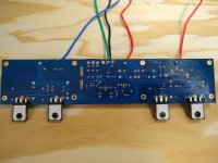
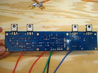
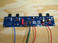
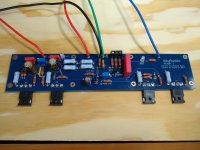
Attached are photos of questionable board.
My next move is to remount the board and see what happens. I'm trying to avoid pulling everything apart repeatedly.
Thanks
Thanks for the quick replies. As for confirming the resistance when soldered to the board, perhaps I misunderstood the build guide for checking the resistance of the soldered in trimpots AFTER all of the components are stuffed on the board. Building: Amp Boards
I am able to adjust the R7 trimpot on the good board to 1 K ohm when it is soldered in and not under a load. This is what got me thinking I had something else going on.
I did just check the JFETS and both sets give similar resistance values across source-drain and source-gate.
I didn't measure the voltage at R27 during power up testing, I measured at R18.
Attached are photos of questionable board.
My next move is to remount the board and see what happens. I'm trying to avoid pulling everything apart repeatedly.
Thanks
Attachments
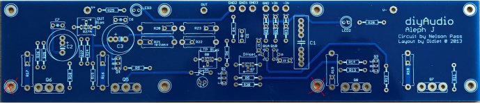
has anybody ever had to enlarge the mounting holes for the amp board ?
i drilled my own heat sinks and I'm finding that my mounting holes are off ever so slightly.
Wondering if I could just enlarge the pcb holes slightly ??
Or are the holes used as a ground or something ?
i drilled my own heat sinks and I'm finding that my mounting holes are off ever so slightly.
Wondering if I could just enlarge the pcb holes slightly ??
Or are the holes used as a ground or something ?
Last edited:
I did, and on the store-provided predrilled heat sinks. Just as large as I needed to get the holes to align. Didn’t have to go too much larger. They aren’t connected to anything electrical that I could tell. Just plated through for strength I presume.
has anybody ever had to enlarge the mounting holes for the amp board ?
i drilled my own heat sinks and I'm finding that my mounting holes are off ever so slightly.
Wondering if I could just enlarge the pcb holes slightly ??
Or are the holes used as a ground or something ?
There are 2 holes that need some attention.... but if you are going to widen the holes just a bit, you'll be okay.
If you widen them too much, or if you use too wide a distancer (stand-off), there's the possibility that either the speaker output signal PCB track, or the V+ PCB track could short to the heatsink (ground)
If you widen them too much, or if you use too wide a distancer (stand-off), there's the possibility that either the speaker output signal PCB track, or the V+ PCB track could short to the heatsink (ground)
Attachments
You can get matched 2sj74 here:
Toshiba 2SJ74 LAB MATCHED QUAD to 0.03mA / 4mV ("B" "BL" 7-9mA Range) | eBay
Would it make any difference between two pairs vs one quad, since we are only using one pair per channel? Do we need to match between both channels?
Thanks for the quick replies. As for confirming the resistance when soldered to the board, perhaps I misunderstood the build guide for checking the resistance of the soldered in trimpots AFTER all of the components are stuffed on the board. Building: Amp Boards
I am able to adjust the R7 trimpot on the good board to 1 K ohm when it is soldered in and not under a load. This is what got me thinking I had something else going on.
I did just check the JFETS and both sets give similar resistance values across source-drain and source-gate.
I didn't measure the voltage at R27 during power up testing, I measured at R18.
Attached are photos of questionable board.
My next move is to remount the board and see what happens. I'm trying to avoid pulling everything apart repeatedly.
Thanks
please resolder your points at all power mosfet´s. they look not really good...then re check
chris
Thanks for the quick replies. As for confirming the resistance when soldered to the board, perhaps I misunderstood the build guide for checking the resistance of the soldered in trimpots AFTER all of the components are stuffed on the board. Building: Amp Boards
My apologies to @Bowlrider. My impression was that the test points around the trimpots would measure correctly after install, but that's seems to have been wrong. I've edited the guide to remove that suggestion. Although, in fairness, I did also say to set the pots *before* installing.
I hope your troubleshooting is successful!
Greetings I have two questions
C6,C7 in the Bill of material were backordered till next year I know they're not necessary but is there any suggestions on other bypass caps?
I'm finding it extremely hard to find 100 watt incandescent light bulbs now that everything's LED will a 60 watt suffice that I have lying around
C6,C7 in the Bill of material were backordered till next year I know they're not necessary but is there any suggestions on other bypass caps?
I'm finding it extremely hard to find 100 watt incandescent light bulbs now that everything's LED will a 60 watt suffice that I have lying around
- Home
- Amplifiers
- Pass Labs
- Aleph J build guide for noobs