They ship from the factory set about halfway. That's good enough.
outstanding
Last edited by a moderator:
Thanks for the posts. When my wife gets home hopefully the thermistors and a few other pieces came. If not I'll just solder wire to the pcb.
If the parts didn't show, should I wire the primary's like shown in the build guide and use a jumper so I'll have -26VDC and +25VDC?
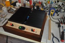
Here's a mock up. I'll run some kind of vented screen down the middle.
Wondering if it will dissipate the heat.
If the parts didn't show, should I wire the primary's like shown in the build guide and use a jumper so I'll have -26VDC and +25VDC?
Here's a mock up. I'll run some kind of vented screen down the middle.
Wondering if it will dissipate the heat.
Attachments
Thanks for the posts. When my wife gets home hopefully the thermistors and a few other pieces came. If not I'll just solder wire to the pcb.
If the parts didn't show, should I wire the primary's like shown in the build guide and use a jumper so I'll have -26VDC and +25VDC?
Here's a mock up. I'll run some kind of vented screen down the middle.
Wondering if it will dissipate the heat.
Woah, nice!
(If this was my project, I‘d make an experiment: how would the thermal problem behave if the base were perforated?—those heatsink work very well with air circulating around/along them, and having them horizontal diminishes airflow considerably)
If the parts didn't show, should I wire the primary's like shown in the build guide and use a jumper so I'll have -26VDC and +25VDC?
Here's a mock up.
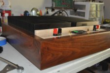
Beautiful wood working.
I'm still confused re: your comments on having only +25VDC.
The power supply is a dual rail supply. One side is + and the other is -
Per previous posts measure below with meter set to VDC:
1) red probe to V+ and black to GND.
2) red probe to V- and black to GND.
If you get +25VDC for 1 and -25VDC for 2...
")
If not, report back.

When I test with the probes as your post yes, I get neg & pos voltage. My question was do I wire it this way, one side reversed.
Can't take any measurements at the moment. Everything's in pieces.
myleftear, I'll punch a bunch of holes in the bottom, 50 or so1/2" dia.
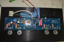
In the pic power goes to V- & V+? Or do I put pwr to the bigger holes in the middle?
Can't take any measurements at the moment. Everything's in pieces.
myleftear, I'll punch a bunch of holes in the bottom, 50 or so1/2" dia.
In the pic power goes to V- & V+? Or do I put pwr to the bigger holes in the middle?
Attachments
I think I'm finally understanding part of your question. I don't know what you mean by one side "reversed", apologies.
Just in case. Each amp board needs V+ and V-. Connections in upper left and upper right of the boards in your picture. Three wires for each board to PSU. V+, V-, and GND.
Is that what you're asking?
Edited to add - there are a few things to potentially discuss re: your amp boards too, but let's cross one bridge at a time.
I don't know what you mean by one side "reversed", apologies.Just in case. Each amp board needs V+ and V-. Connections in upper left and upper right of the boards in your picture. Three wires for each board to PSU. V+, V-, and GND.
Is that what you're asking?
Edited to add - there are a few things to potentially discuss re: your amp boards too, but let's cross one bridge at a time.
Last edited:

I think I'm finally understanding part of your question.
Just in case. Each amp board needs V+ and V-. Connections in upper left and upper right of the boards in your picture. Three wires for each board to PSU. V+, V-, and GND.
Is that what you're asking?
Edited to add - there are a few things to potentially discuss re: your amp boards too, but let's cross one bridge at a time.
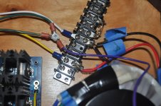
I was talking about the connection at the terminal strip.
Mail was picked up but no connector blades or thermistors so, I'll solder wires to the pcb. Then I'll do the DBT and check for voltage and report back.
Test complete. +26.26VDC & -26.26VDC when test leads are reversed on the neg side.
If I measure pos to neg. on both sides both measurements are positive hence my question about the terminal block connections. As is I have + paired & neg. paired. If I wire these like I'm supposed to and don't have a thermistor should I use a jumper for the time being?
If I measure pos to neg. on both sides both measurements are positive hence my question about the terminal block connections. As is I have + paired & neg. paired. If I wire these like I'm supposed to and don't have a thermistor should I use a jumper for the time being?
^ compare that to your board.  Many people typing. That nod was to point to 6L6's post.
mkane77g - re: my previous note. That's one of the things I left as future bridge to cross later. See the jumper configuration while you've got the iron hot. With your post in the middle, it loses context. I mean the input jumper.
Many people typing. That nod was to point to 6L6's post.mkane77g - re: my previous note. That's one of the things I left as future bridge to cross later. See the jumper configuration while you've got the iron hot. With your post in the middle, it loses context. I mean the input jumper.
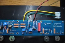
Amp board input wiring -
RCA center to +IN, RCA ring to GND, jumper -IN to GND.
Attachments

When I test with the probes as your post yes, I get neg & pos voltage.
This statement...
Test complete. +26.26VDC & -26.26VDC when test leads are reversed on the neg side.
If I measure pos to neg. on both sides both measurements are positive...
...and this statement do not agree with one another. Which is it?
This statement...
...and this statement do not agree with one another. Which is it?
Both of my statements are suppose to read the same.
Put black probe on PSU GND.
Red probe to V+, meter should read positive.
Red probe to V-, meter should read negative.
Does it?
yes and the amps wired ready to set trim pots
- Home
- Amplifiers
- Pass Labs
- Aleph J build guide for noobs