I have been enjoying F5 and ACP for months now. I have build the chassis for ACP, remote trigger, switch and all works like charm, except...
I get hum from speakers. If nothing is connected or if only one channel (either one) is connected the amp is dead quiet. As soon as I connect second channel the hum appears. If I connect Chord Mojo directly, same outcome.
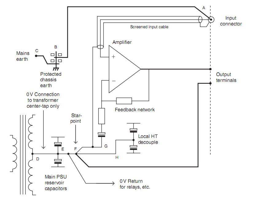
I did the test shown in this file and connected the inputs directly and hum appeared, same level.
Can you good people recommend any solution?
For internal wiring I used Mogami W2549 AWG22. Above linked PDF suggests using AWG14 wire for internal wiring to avoid Cross channel ground loop.
Any recommendations for the wires?
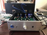
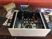
Here are the pictures if somebody can see something obviously wrong:
I get hum from speakers. If nothing is connected or if only one channel (either one) is connected the amp is dead quiet. As soon as I connect second channel the hum appears. If I connect Chord Mojo directly, same outcome.
I did the test shown in this file and connected the inputs directly and hum appeared, same level.
Can you good people recommend any solution?
For internal wiring I used Mogami W2549 AWG22. Above linked PDF suggests using AWG14 wire for internal wiring to avoid Cross channel ground loop.
Any recommendations for the wires?
Here are the pictures if somebody can see something obviously wrong:
Attachments
Try a big fat wire between the two gnd connections on the RCA jacks on the amp. That may break the ground loop before it reach the amp.
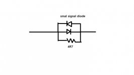
you could also isolate the signal gnd from the amp gnd using a 4.7ohm(ish) resistor an 2 smal diodes. Diodes in paralell in opposite direction of each other and the resistor in paralell with the diodes and connect it in series with the signal gnd.
you could also isolate the signal gnd from the amp gnd using a 4.7ohm(ish) resistor an 2 smal diodes. Diodes in paralell in opposite direction of each other and the resistor in paralell with the diodes and connect it in series with the signal gnd.
Last edited:
you need to try that fat wire bridge between two channel pcb GND points, power ones, not signal ones
while you're there , with that bridge removed - you can try simplest of cures - desolder one GND (shield) from RCA , insert 15R MF resistor there in series , so you'll end with one channel having straight GND while second having 15R inserted
while you're there , with that bridge removed - you can try simplest of cures - desolder one GND (shield) from RCA , insert 15R MF resistor there in series , so you'll end with one channel having straight GND while second having 15R inserted
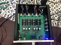
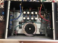
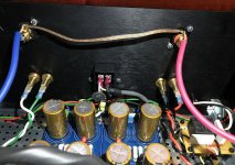
Looking at the picture of your power supply board you have both board ground points jumpered together.By that I mean the ones on the power supply board closest to the transformer ( 2 bare wire jumpers) and the ones on the power supply board closest to the back panel( 2 bare wire jumpers).If you look at the schematic of the diy power supply board you have you will see what you have done is create a loop.Remove the 2 little jumpers from the end of the board closest to the transformer.Your star ground point is to be where the remaining jumpers are (2 bare wire jumpers closest to the back panel).This point goes to your board grounds and also thru a CL60 to the power plug ground.
Last edited:
I tried 2 parallel 39 ohm resistors on left channel and right channel would go quiet but left channel hum would increase. I then tried resistors on right channel and same would happen. Left quiet, right humming louder. I then added third resistor with no change to hum.
Attachments
Looking at the picture of your power supply board you have both board ground points jumpered together.By that I mean the ones on the power supply board closest to the transformer ( 2 bare wire jumpers) and the ones on the power supply board closest to the back panel( 2 bare wire jumpers).If you look at the schematic of the diy power supply board you have you will see what you have done is create a loop.Remove the 2 little jumpers from the end of the board closest to the transformer.Your star ground point is to be where the remaining jumpers are (2 bare wire jumpers closest to the back panel).This point goes to your board grounds and also thru a CL60 to the power plug ground.
PCB's have ground plane full length front to back. I do not think that round loop would be created in this area.
PCB's have ground plane full length front to back. I do not think that round loop would be created in this area.
Look at the schematic for this board, it doesn't have to be round to be a ground loop,just connected in a loop which is what happens when you jumper D-1 and D-2 at one end and GND2 and GND3 at the other end.Due to the currents in the capacitors there will be a difference in potential between the D end and the GND end.The currents albeit pulses can be 10's of amps.If you don't believe me sim it in LTSpice and you will see for yourself,i have a sim and when the 2 ends are joined there is current,lots of it.When I remove one end of the "loop" the current goes away.If I can figure out how to post my sim results you will see but please believe me,i'm not making this up.
I tried 2 parallel 39 ohm resistors on left channel and right channel would go quiet but left channel hum would increase. I then tried resistors on right channel and same would happen. Left quiet, right humming louder. I then added third resistor with no change to hum.
Try something like this in series with signal gnd. solder it at the amp gnd point.
Attachments
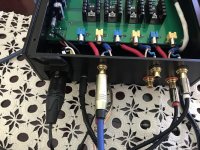
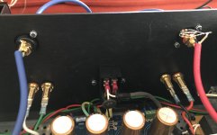
these wires aren't connected as screened cable?
and they're not twisted
tried any of these?
Screen is connected at the amp module to negative cable of the signal. Internal wires are twisted but last 1-1.5cm.
This is Mogami 2549 cable. I use it to make interconnects and always connect only one side of the screen. Both Van den Hul (page 10) and Audioquest (Step 2) recommend removal of the screen (or drain wire) on the source end to avoid ground loop.
I think PS audio recommends similar.
Attachments
Try something like this in series with signal gnd. solder it at the amp gnd point.
I tried this on input and it did not make difference. Do you think it would be different enough to try on the amp side?
There's no need for the diodes, they're only necessary on chassis ground to carry fault currents.
If a screen is only connected at one end it's usually at the source.
Connected the shield on the input too and no change.
Doug Self's schematic is similar Grounding System In Power Amplifiers - DIY AUDIO BLOG, AUDIO WORKSHOP
Why connect input connector + to mains earth?
- Home
- Amplifiers
- Pass Labs
- F5 Cross channel ground loop