You are right. Here is the updated schematic.
View attachment Cap Multiplier JM.pdf
The current version of the PCB layout is perhaps being squeezed smaller than it needs to be. (There layout certainly is nice and tight.) Sometimes it's nice to have some breathing room around components that may still be experimental in the implementation. I'm thinking in particular of the capacitor C72 at the output of the cap Mx / Drain of the SIT. It may be preferable to allow for a 10,000 uF electrolytic at this location. Or to give the option of experimenting with 2700 uF wire lead vs the larger snap-in component.
That's an interesting cap multiplier. I might recommend the KSC2690 or ZTX855 for Q3 and the NJW3281G or MJW3281A for Q4, for their lower saturation voltage. This will reduce the dropout voltage of the cap multiplier. The KSA992 is also a good substitute for the BC557.
All recommended substitutions are fine. Only Q3 needs consideration because it's gain plays a vital role in multiplying the 100uF capacitance in its Base.
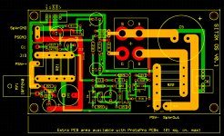
My PCB fabricator (ExpressPCB.com) has a size limit of 21 square inches for the ProtoPro category of boards that I order. The PCB is currently 5.5" x 3.1" = 17.05 square inches, so there is room to expand it a bit. However I view that extra space as for emergency use.
My feeling is that a more complicated capacitance multiplier should be on a different PCB. Simulations of the existing cap. multiplier with a power supply like I used for my build of a SIT-2 variant show V+ ripple reduced from about 150mV PP to 1.4mV PP, and ripple at Vout of 250uV PP. The main downside of that cap. multiplier is the 4.8V voltage drop.
My feeling is that a more complicated capacitance multiplier should be on a different PCB. Simulations of the existing cap. multiplier with a power supply like I used for my build of a SIT-2 variant show V+ ripple reduced from about 150mV PP to 1.4mV PP, and ripple at Vout of 250uV PP. The main downside of that cap. multiplier is the 4.8V voltage drop.
Going back to the circuit with the missing connection, if you don't mind the voltage drop (& extra heat), swap positions of VR1 & C1 and increase its value to 220uF, replace VR1 with a TL431, replace the missing connection with a 4K7 resistor, and connect he TL431 feedback resistor to the output... and add a cap Where C1 use to be. Just shave half a volt off.
Last edited:
Here is a PCB layout expanded 0.2" horizontally, and showing the extra space available at the bottom at the 21 sq. in. limit. Other trade-offs are available, such as making it wider to the left. Clearly there is a fair amount of room available if there is a really good reason for it.
Attachments

You are right. There need to be pot adjustments associated with with either R8 and R9 or R31 and R32.How is the Vgs bias set for M1 and M2?
Maybe one pot with R37 would do it.
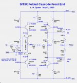
Calling all capacitor wizards:
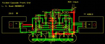
The SIT3X output stage can be used in two modes:
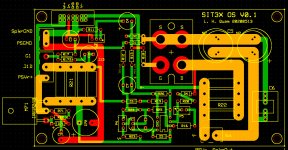
Is a pair of 4.7mF capacitors preferable to one 10mF capacitor?
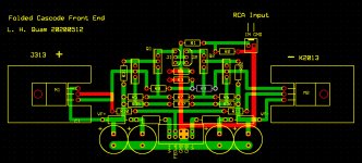
Below is a PCB layout that permits either choice.
The SIT3X output stage can be used in two modes:
- Vraw+ at +47V, V- at -47V, FET sources at about -3V
- V+ at ground, V- at -94V, FET sources at about -47V.
Is a pair of 4.7mF capacitors preferable to one 10mF capacitor?
Below is a PCB layout that permits either choice.
Attachments
Calling all capacitor wizards:
The SIT3X output stage can be used in two modes:
What should used for the output capacitor? Option 2 clearly calls for a 50V or higher electrolytic. For option 1, would a 10V non-polar capacitor be preferred to a 50V electrolytic?
- Vraw+ at +47V, V- at -47V, FET sources at about -3V
- V+ at ground, V- at -94V, FET sources at about -47V.
Is a pair of 4.7mF capacitors preferable to one 10mF capacitor?
Below is a PCB layout that permits either choice.
First let me thank you for sharing all your work with us. Outstanding job, as usual.
I am not a wizard, but according to the Richard Marsh/Walt Jung cap research back in the 1980s, we should allow on the board bypassing of the large electrolytic cap with 10 mf+ 5 MF+ .5 MF Polypropylene and Polystyrene caps. Lately most people are using just one 5 MF Polypropylene, but we should have some space for bypassing.
Your question was about one or two caps and I am guessing two caps are better than one, but the cap choice may be more important than how many, ripple current, ESR, other parameters that I don't fully understand are in play.
Thanks again for sharing,
Rush
This is going to be a can of worms. The only non- or bi-polar electrolytic caps that I trust are the Nichicon ES series. Unfortunately, these top out at 1000 uF. That's why you don't usually see the bi-polar parts being used for speaker output coupling. The recommended minimum voltage rating would be 16V, and 25V would be better.
Polar electrolytic can be Nichicon KW or KA for wire leads, or Nichicon KG and KS series for snap-in leads. I think it's Ok to use either a single 10,000 uF or a pair of 4700 uF parts. Most folks will want to bypass these with high-quality film caps, though I have gone both ways (w/ and w/o) on this.
Polar electrolytic can be Nichicon KW or KA for wire leads, or Nichicon KG and KS series for snap-in leads. I think it's Ok to use either a single 10,000 uF or a pair of 4700 uF parts. Most folks will want to bypass these with high-quality film caps, though I have gone both ways (w/ and w/o) on this.
Last edited:
Here are some caps I am considering:
- Panasonic 6.8mF 6.3V bipolar ECE-A0JN682U. 18mm D, 7.5mm LS.
- Panasonic 4.7mF 10V bipolar ECE-A1AN472U. 18mm D, 7.5mm LS.
- Nichicon 4.7mF 10V bipolar UVP1A472MHD. 18mm D, 7.5mm LS.
- Nichicon 3.3mF 16V bipolar UVP1C332MHD.18mm D, 7.5mm LS.
- Panasonic 3.3mF 16V bipolar ECE-A1CN332U.18mm D, 7.5mm LS.
- Nichicon 6.8mF 50V polar UVP1A472MHD. 22mm D, 10mm LS. Audio Grade.
- Nichicon 6.8mF 50V polar LLS1H682MELZ. 22mm D, 10mm LS. Snap-in.
- Nichicon 6.8mF 50V polar UVR1H682MRD. 22mm D, 10mm LS. Leaded.
How about this.
LKG2A103MKZ Nichicon | Capacitors | DigiKey
Or for less money
382LX103M100A082 Cornell Dubilier Electronics (CDE) | Capacitors | DigiKey
LKG2A103MKZ Nichicon | Capacitors | DigiKey
Or for less money
382LX103M100A082 Cornell Dubilier Electronics (CDE) | Capacitors | DigiKey
Last edited:
- Home
- Amplifiers
- Pass Labs
- The SIT-3X Amplifier