it'll work
Hi ! thank you very much indeed. I will also lower the R101 value to keep the +15V after that.
I will get it in the next days and post some photos ... horrible photos i am afraid

Thanks again and kind regards, gino
Hi just out of curiosity. Did anyone try the BOZ as a unity gain buffer (ie. taking the signal out of mosfet source pin) ?
In my application gain is not needed ... just volume control and buffering. I am using the volume pot at the input
I wonder how good it would be in sonic terms.
Thanks a lot.
In my application gain is not needed ... just volume control and buffering. I am using the volume pot at the input
I wonder how good it would be in sonic terms.
Thanks a lot.
after reading great things about the sound performance of the B1 buffer designed by Nelson Pass I wonder how good the BOZ would be configured as a unity gain buffer, i.e. with the signal taken from the mosfet pin source.
Did anyone try it this way ?
im my recent applications voltage gain is really do not needed
therefore i am evaluating different buffer solution actually
Did anyone try it this way ?
im my recent applications voltage gain is really do not needed
therefore i am evaluating different buffer solution actually
Hi ! sorry ... but still on the BOZ
i have a very quick question ... can the +8V needed in front of R106 be obtained with a simple voltage divider from the +60V coming from the power supply ? maybe using a multiturn trimmer to have some control during setting ?
Moreover ... is the IRF610 still the more suitable part to use ?
I am sorry to resurrect this very old thread but this BOZ really deserves to live forever. I am impressed by its simplicity at the point that i think it will be my final line preamp
I am just thinking to reduce a little the gain and even parts
The challenge is to provide to the circuit a very very clean Voltage (i.e. noiseless)
Imho the Bride of Zen is a milestone in the DIYaudio history
Attachments
Last edited:
it is already exactly as you asked - got with divider from 60V
you're probably confused with "15V" - that's just potential you can expect here, not separate supply
Hi ! please excuse me if i take up this maybe old design again ... but i am banging my head against the wall asking myself ... why is the BOZ not more popular ?
I am evolving towards a Zen approach to high fidelity ... seeking simplicity as much as possible ... trying to prune designs already very good indeed
If one part can replace two i would go for that single part ...
It seems like all DIYers have forgotten this nice sounding line stage ... does it have some issues that i do not know ?
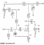
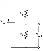
Speaking instead of voltage dividers ... i had in mind the one attached
Very basic ... two resistors with maybe one of the two replaced by a 10 turn trimmer to have a precise control on the setting
The one in the schematic looks more complex to me. Is there a particular reason for that complexity ? i see maybe a RC filter ?
Have you ever used a BOZ ? what is your opinion in general ?
I would love to hear from people who have been exposed to it and understand why they have moved to something else ... what they were missing with the BOZ ?
Imho the potential upgrade could be found in the power supply
Personally i would like to use a smps unit i have at hand with some eventual passive filtering before the circuit
I decided for a smps because i have been told that most of the noise (usually around 100-200mV) is located outside the audio range and it can be suppressed quite easily with some passive RC or LC network ... very convenient when a single supply voltage is required
thanks a lot, gino
Attachments
Last edited:
voltage potential there must be constant and steady, not influenced with signal, that's why there is "complexity"
build it and play with , easier and more useful way of learning than asking trivial things on forum
start reading all articles at First Watt / articles - you'll learn a ton, while having fun
build it and play with , easier and more useful way of learning than asking trivial things on forum
start reading all articles at First Watt / articles - you'll learn a ton, while having fun
voltage potential there must be constant and steady, not influenced with signal, that's why there is "complexity"
build it and play with , easier and more useful way of learning than asking trivial things on forum
start reading all articles at First Watt / articles - you'll learn a ton, while having fun
Thank you .... still i do not understand what you mean really
1st theory ... then practice How can i hope to build something if i do not understand what i am doing ?
For instance ... can i use a battery to provide 9V instead of 8V in front of the Mosfet ? like for tubes ?
It seems to me that people have moved on from this design without a reason
Is the schematic proposed the best possible for a single mosfet line stage ?
If so ... issue closed of course
Attachments
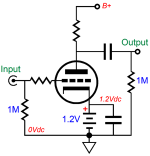
The 8V is not something you set as a target, but rather just a nominal value
you might measure when the mosfet is biased up to 40mA by adjusting P102.
Take two random IRF610 and you'll likely see two different values.
I built a Boz and had a couple of issues. I tried a couple 5K pots for
the volume control and they weren't that well balanced. Also, the input
was susceptible to input overload with my CD player so I needed to add
attenuation at the input. The Boz sounded good but ultimately I went back
to my existing preamp because it had a built-in phono stage.
The Boz is an old design and many people may simply not be aware of it.
Also PCBs are no longer readily available, which may dissuade some
from trying it. Beyond that, people often just like to build new things.
I recommend you look up the Aleph L schematics and compare it to the Boz.
The 8V is not something you set as a target, but rather just a nominal value you might measure when the mosfet is biased up to 40mA by adjusting P102.
Take two random IRF610 and you'll likely see two different values.
Hi ! thank you very much for your kind and valuable reply. So the schematic cannot be simplified even further. It is already as minimalist as possible.
I am asking because i do not have a clue of course.
I was just wondering about alternative schematics like the one attached Will it work just the same ? that is much easier
I see. I played some years ago with a prototype i must still have somewhere I had a disastrous move during which many things were lost and now they are stored aways badly.I built a Boz and had a couple of issues. I tried a couple 5K pots for
the volume control and they weren't that well balanced. Also, the input
was susceptible to input overload with my CD player so I needed to add
attenuation at the input.
I used a 20K log stepped attenuator and the input and loved the sound. The gain was a little on the high side ... but the attenuator was working very well even with high attenuation settings It was of the series resistors type (Holco resistors)
Thanks a lot again. I will look for the Aleph L then I hope it will not be more complicatedThe Boz sounded good but ultimately I went back
to my existing preamp because it had a built-in phono stage.
The Boz is an old design and many people may simply not be aware of it.
Also PCBs are no longer readily available, which may dissuade some
from trying it. Beyond that, people often just like to build new things.
I recommend you look up the Aleph L schematics and compare it to the Boz
Kind regards, gino
Attachments
Last edited:
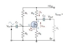
I have a question about the input attenuator and I'm asking for advice.
Gain, despite the changes in the R104 / R108 resistors, was too big so, on the advice of my friends from another forum, I made a 1k / 400R attenuator at the output. However, it is only needed for the CD input, so I made it at the input (see picture).
Is that a good solution?
D.
Gain, despite the changes in the R104 / R108 resistors, was too big so, on the advice of my friends from another forum, I made a 1k / 400R attenuator at the output. However, it is only needed for the CD input, so I made it at the input (see picture).
Is that a good solution?
D.
Attachments
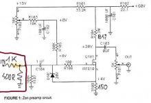
voltage divider 1k+400ohms gives you an imput impedance around 1,3xxx kohms..................way too low for hifi gear.
use multiples of these, e.g. 4,7 times ,
so 4,7k instead of 1k and 1,8k for 400 ohms.
aside this you can increase the 150 ohm source res to 180 ohms or so what
and trim the drain volts again.......this lowers the voltage gain a little bit.
use multiples of these, e.g. 4,7 times ,
so 4,7k instead of 1k and 1,8k for 400 ohms.
aside this you can increase the 150 ohm source res to 180 ohms or so what
and trim the drain volts again.......this lowers the voltage gain a little bit.
Thank you
As I wrote, only the CD input needs attenuation so I will not interfere with the circuit anymore. I am happy how BoZ sounds and what the waveforms look like. Of course, I will change this voltage divider on the input as you advised.
Maybe 10k/4k3 will be better?
This is the 1k / 400r gain on the oscilloscope
Last edited:
I have a question about the input attenuator and I'm asking for advice.
Gain, despite the changes in the R104 / R108 resistors, was too big so, on the advice of my friends from another forum, I made a 1k / 400R attenuator at the output. However, it is only needed for the CD input, so I made it at the input (see picture).
Is that a good solution? D.
Hi ! sorry to jump in with questions more than solutions
I have been thinking a lot about lowering the BOZ gain as well. ... as a Vgain of 6 times is way too much for a line stage when 2-3 times is more than enough i think
But as long as an attenuator is transparent and of the right value i do not understand this idea of putting the volume pot at the output obtaining a Zout variable with the pot position
So i tried a 20klog stepped attenuator (the series resistors kind) at the input and the sonic result was quite ok
Anyway i am always wondering which would be the best way to lower the stage gain ... i have no clue.
I was even thinking to lower Vsupply and replace R104 with a lower value resistor.
If i use for instance a 40V supply i could halve R104 ?
But i would really think about placing the volume at the input. A good one of course
Last edited:
My output potentiometer is the active Baxandall volume control. This is a similar circuit to the TI active volume controller. According to the designer, it has high input impedance and low (a few ohms) output. Maybe I'll just put it on the BoZ input? If so, what resistor should I put on output instead of a potentiometer?
- Home
- Amplifiers
- Pass Labs
- Bride of Zen, Bride of Son of Zen