Hello, I have build my first Aleph 5. Schematic bellow. I have matched IRF9610. Rail voltage +-34V
I have start with just one pair of IRF244 before adding others. When I connect dummy load 8Ohm, everything seems OK. 13v peak to peak before clipping- that is power output I would expect.
When clipping started around 14.5V, it clipping only postive side of sinewave, negative is ok even in much higher output. Somehow assymetric clipping... If I have added more output mosfets, clipping was symetric. With just one pair, always such assymetric - however same behaviour on both channels. Is it something I should deal with?
If I connect 6Ohm speaker instead of dummy load, there is quite big oscillation - 600Khz. Suprisingly, if I lower rail voltage to +-10V, everything going nice. No Oscilation and THD even lower then with +-34V, maximum output voltage cca 14V pk-pk. However, when rail voltage go over +-15, imediatelly there is big 600Khz oscilation.
As it is my first Mosfet amplifier, Im little bit lost how to prevent the oscilation. Im thinking to try increase gate serial resistor from 221 to 1K. Thinking to add some capacitors between Gate and source...however not really sure where to focus first.
Really appreciate any help from more experienced guys here, what should I try. Thank you in advance.
Attachments
two 1nF caps will probably cure whatever you have there
see enclosed
Thank you for quick answer. As I see in the schematic, there are two 1nF caps.
C105 - In my circuit is 680pF. Quite close to 1nF, so Im not expecting there should be any change if I replace it.
C102 - I have added 1nF there. Unfortunatelly, it did not stop the oscilation.
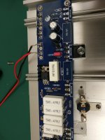
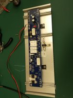
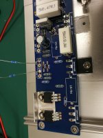
PCB is from HIFISTOR Aleph 5 60W A class Amplifier D.I.Y. - HiFiStorPlease post some well-lit, in-focus photos of your amp so we can start looking at what you have.")
Some components I used from kit, some resistors I replaced with more precise and matched IRF9610. I tried to swap IRFP244 multiple times. Somehow, the amplifier is more stable with 2- pairs of transistors and has even clipping than with one pair. However, due to smaller heatsink and enough power to drive my speaker just with 10W, I would like to make it run on one pair only.
What is not visible, I added 1nF from bottom C102.
Attachments
Also to mention, right now Im just using as rail power Lab power supply Fluke +-60V / 5A. Im not expecting any issue from here.Thank you for quick answer. As I see in the schematic, there are two 1nF caps.
C105 - In my circuit is 680pF. Quite close to 1nF, so Im not expecting there should be any change if I replace it.
C102 - I have added 1nF there. Unfortunatelly, it did not stop the oscilation.
If the amplifier has no input, it stays ok. when I connect any source to input, even just wires without any signal (generator turned off) it start oscillating.
Hi Alex 97,
The quiescent current would depend on the number of devices used in the output; the correct number of output devices would set the correct quiescent current, and hence -> you'd achieve the symmetrical clipping. Therefore, use 3 output devices, i.e. 3 x 1 ohm wire-wound resistors in parallel. This 0.33ohm value, together with that 1k resistor picking up the voltage drop across 1-ohm resistor & biasing the base of MPSA18, will set the correct operating point of the output stage.
The quiescent current would depend on the number of devices used in the output; the correct number of output devices would set the correct quiescent current, and hence -> you'd achieve the symmetrical clipping. Therefore, use 3 output devices, i.e. 3 x 1 ohm wire-wound resistors in parallel. This 0.33ohm value, together with that 1k resistor picking up the voltage drop across 1-ohm resistor & biasing the base of MPSA18, will set the correct operating point of the output stage.
Last edited:
Hi Alex 97,
The quiescent current would depend on the number of devices used in the output; the correct number of output devices would set the correct quiescent current, and hence -> you'd achieve the symmetrical clipping. Therefore, use 3 output devices, i.e. 3 x 1 ohm wire-wound resistors in parallel. This 0.33ohm value, together with that 1k resistor picking up the voltage drop across 1-ohm resistor & biasing the base of MPSA18, will set the correct operating point of the output stage.
Thank you for answer. As Im still learning the pass aleph topolopogy, I was not sure how to properly bias it. So thx for pointing it out.
With 1ohm resistor, the amp is taking 0.5 Amp per transistor pair. With 3 pairs, 1.5 Amp. If I keep only one pair of transistor and lower value of the resistor to , 0.33 ohm the amp should draw more current, cca 2 Amps. That would drive transistors too hot. So I think, I should keep 1 ohm, but play more with the value of 1K resistor. Is it right idea? I will try some potenciometr there and see if I can find balance.
Yes, exactly right. However, you will also change the AC gain by playing with a 1-ohm resistor. Nelson has explained how to empirically set the AC gain, so you can set the quiescent current properly, for symmetrical clipping, AND set the AC gain at 50% which seems like a desired amount of gain.
Yes, exactly right. However, you will also change the AC gain by playing with a 1-ohm resistor. Nelson has explained how to empirically set the AC gain, so you can set the quiescent current properly, for symmetrical clipping, AND set the AC gain at 50% which seems like a desired amount of gain.
So I end up to have 1 Ohm resistor (0.5A current) together with 2.2K resistor instead of 1K. I was not going mainly for symetrical clipping, but measure for best THD regrding almost max power output. With 2.2K I get best THD and also clipping symetry get much better even it is still somehow assymetric. So thank you for help with biasing.
So main issue stay to be 600KHz oscilation when connected to speakers. Still trying to eperiment with it, however without success yet
Several suggestions:
With lab supply, consider some capacitance from rails to ground
Doesn't oscillate without a source? what if you short the input to ground?
Oscillates with load? How about with about .1 uF + 5 ohms to ground?
Hello Nelson, thank you for great design.
It is strange, never see such behaviour with amp before. But first time building Mosfet amp. It doesnt oscillate if I use just dummy 8ohm load.
When I attach speakers, it starts oscillating 300-600KHz 10-20V pk-pk. It is oscillating even when no source or inputs shorted to ground. If no load or full load, the value doesnt change.
I tried to see what happening on rails. POSITIVE to GND nothing. GND to NEGATIVE - 4Vpk-pk 300-600KHz noise.
If I try different lab supply, same behaviour.
Something strange going on negative rail.
I note this is a likely known issue since the Aleph 3: Aleph 3 oscillations
I'd never recommend avoiding rail decoupling, its first and strongest defence against unwanted positive feedback paths. I note the Aleph P uses decoupling on at least one rail.
Skimping on this because it happens to work in a particular configuration is, erm, questionable, to say the least.
I'd never recommend avoiding rail decoupling, its first and strongest defence against unwanted positive feedback paths. I note the Aleph P uses decoupling on at least one rail.
Skimping on this because it happens to work in a particular configuration is, erm, questionable, to say the least.
- Status
- This old topic is closed. If you want to reopen this topic, contact a moderator using the "Report Post" button.
- Home
- Amplifiers
- Pass Labs
- ALEPH 5 Oscilating 600KHz