Will do!!! While I talked to him last night I didn't know but he has been following this thread after I mentioned I had posted on this forum for help. I will asked him so it may help the next guy that runs into this issue which I'm sure he will he's a very nice guy. For future reference if I do get amp back am I understanding that the gain can be increased by changing out resistors? Am I reading correctly the stock gain on Pearl 1 is 30db and if it can be increased higher with resistor swap? If so how much gain can be achieved?
I’m the builder and am following along. When I get to back, I will post what I find.
Given the measurements posted and the fact that both channels are equally under voltage — they measured perfectly when I built it — I suspect power supply. I hope it will be an easy diagnosis and repair.
Given the measurements posted and the fact that both channels are equally under voltage — they measured perfectly when I built it — I suspect power supply. I hope it will be an easy diagnosis and repair.
Please invite the original builder to post in this thread, I’m sure we are all curious as to what’s happening and would very much like to help.

Am I reading correctly the stock gain on Pearl 1 is 30db and if it can be increased higher with resistor swap? If so how much gain can be achieved?
Gain was supposed to be in the 50's, as per the original article.
jeff
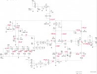
I received the Pearl and have started the diagnosis. I found a problem, but not the cause, yet. Measuring the voltage at Q4 I get 0.8 V on both channels. Much lower than the expected 13.8 V.
The voltages elsewhere aren't perfect, but are closer to correct. Both channels measure almost exactly the same, so I'm reporting only one:
1) The 30V transformer is putting out 37 V AC, which is high. This may be because Plitron specs 115V input, but I'm a little surprised.
2) The power supply is consequently putting out 48 V DC. This is also high, but expected given the higher than expected AC.
3) The drop across R2 is 0.3 V (should be 0.25 V)
4) Voltage at R8 is 28.5 V (should be 29V)
5) Voltage at Q3 is 24 V (should be 24.6)
6) Voltage at Q5 is 10.9 V (should be 11.7)
A few more relevant details. I build the Pearl about 15 years ago and used it extensively for 10 years in my main system with a Rega Super Elys high output cartridge. I'm enough of a perfectionist that I wouldn't have let it leave the bench if it didn't measure correctly. I never had a problem until I replaced my amp with an NAD d3020. Immediately the volume on the turntable was too low, which I assumed was due to the amp. It now appears something went wrong with the Pearl concurrent with the amp switch. It's mysterious to me how both channels failed in the same way at the same time.
But because it used to work I'm assuming a component failure. I don't see any obvious scorching, blown resistors, smoke, leaking caps, etc. And it still plays, just super low volume. I'll keep investigating and posting.
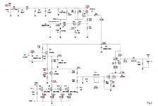
I tested Q4 using the multimeter test on:
Testing transistors with DMM or VOM
and I get 0.7 V as expected for the red to base, black to emitter reading. I get 1.7 V for the black to base, red to emitter test instead of "open". Same with the collector to emitter test -- 1.1 V instead of "open". I don't have another ZTX 450 to compare to whether not getting "open" is a failure or is expected for this device. Except for the other bipolar on the board. All read some nominal voltage instead of "open".
Last edited:
0.8 V, much too low.
What is DC voltage at the emitter? (Where it says 13.8v)
The full pdf for the original Pearl manual is hidden but lives at:
https://www.passdiy.com/pdf/pearlphono.pdf
https://www.passdiy.com/pdf/pearlphono.pdf
Thanks!
I've checked all the resistors and all measure close to the spec'ed values. I've checked all the transistors by the diode test method, which may not be optimal, but all measure consistently with the other devices on the board.
I don't have an LCR meter to measure the caps. I do have a device tester I can use if I desolder.
Not suspicious at all as it has the output diff pair and it’s source resistor in parallel...
I've checked all the resistors and all measure close to the spec'ed values. I've checked all the transistors by the diode test method, which may not be optimal, but all measure consistently with the other devices on the board.
I don't have an LCR meter to measure the caps. I do have a device tester I can use if I desolder.

Ok , Wayne already did all the job needed
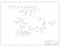
pic pulled from pdf (one you can find linked few posts above) and I did mark with red all voltages
compare with yours , if something is different - mark on pic with different color and post here
+/-10% differences are normal and OK , everything higher than that can be suspicious
pic pulled from pdf (one you can find linked few posts above) and I did mark with red all voltages
compare with yours , if something is different - mark on pic with different color and post here
+/-10% differences are normal and OK , everything higher than that can be suspicious
Attachments
Last edited:
- Status
- This old topic is closed. If you want to reopen this topic, contact a moderator using the "Report Post" button.
- Home
- Amplifiers
- Pass Labs
- Help, Pass Lab Pearl 1, gain is gone both channels