hello,
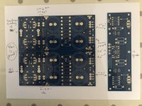
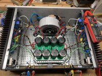
Could i ask an experienced Diyer to help me with my first F5 build please? I bought a 500VA 2x18v (not center tapped) and the boards from DiyAudio as shown in the picture. i just want to check all the connections and the grounding. Could you please look at my diagram and see if it is correct? I don't know how to ground it though? for my preamp, i take the ground from the transformer to the chassis and connect all grounds from the PSU board etc to that single point. How do i connect the transformer leads to the board and how do i ground everything? thank you very much
Could i ask an experienced Diyer to help me with my first F5 build please? I bought a 500VA 2x18v (not center tapped) and the boards from DiyAudio as shown in the picture. i just want to check all the connections and the grounding. Could you please look at my diagram and see if it is correct? I don't know how to ground it though? for my preamp, i take the ground from the transformer to the chassis and connect all grounds from the PSU board etc to that single point. How do i connect the transformer leads to the board and how do i ground everything? thank you very much
Attachments
Here is some information:
diyAudio Power Supply Circuit Board v3 illustrated build guide
One transformer secondary is connected to AC1A and AC1B and the other secondary is connected to AC2A and AC2B.
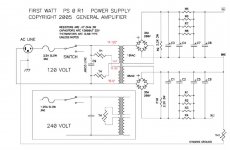
Grounding as shown on typical First Watt Power Supply schematic:
diyAudio Power Supply Circuit Board v3 illustrated build guide
One transformer secondary is connected to AC1A and AC1B and the other secondary is connected to AC2A and AC2B.
Grounding as shown on typical First Watt Power Supply schematic:
Attachments
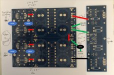
I did a little markup of the picture you posted. See the Power supply schematic above, too.
Each pair of secondaries goes onto the 18V circles on the markup. Use tabs for easy removal. Mouser part number 538-19708-4013 worked for me.
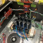
The red lines on the board are the wires you'll bridge. I have used stripped romex for this. On the right side of the drawing that vertical red is connecting the 2 rails to make the ground point. You can see the ground to the speaker, the F5 board coming off there. Also put a CL-60 Thermistor there connected to chassis ground. Using molex connectors is nice for attaching wires on that end of the board. Mouser part 538-39890-0303
Each pair of secondaries goes onto the 18V circles on the markup. Use tabs for easy removal. Mouser part number 538-19708-4013 worked for me.
The red lines on the board are the wires you'll bridge. I have used stripped romex for this. On the right side of the drawing that vertical red is connecting the 2 rails to make the ground point. You can see the ground to the speaker, the F5 board coming off there. Also put a CL-60 Thermistor there connected to chassis ground. Using molex connectors is nice for attaching wires on that end of the board. Mouser part 538-39890-0303
Attachments
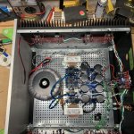
You can see the ac in on these pix, and zoom in for romex. This is a F5 Turbo, so the ground isn’t just a cl60. But concept is similar, green wire to cl60 to chassis. You can solder one leg of the Cl60 to the board then run a wire from the other leg to the chassis.
Attachments
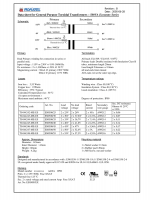
Thank you so much. I bought this transformer Security Check. Bearing in mind that i live in the UK so it's 230v, could you please tell me how i connect this to the rectifier? I know DIYaudio says that it needs to be a center tapped but this does not have it. Also, in the schematic for the power supply, ground runs off a common point for the rectifier and the capacitors, which point is that on the psu pcb? In the diyaudio build, they seem to suggest bridging all the ground points together with metal clips, i don't think this is necessary right? in your mark up, the red bridges do not connect all the holes. (or do they?)
looking at attached file
connection goes as :
230Vac mains :
Red to Phase
Black & Brown tied and isolated
Blue to Neutral
Secondary, connection as Center Tapped:
Yellow is AC(1) to Diode Bridge
Green & Violet tied , that's CT , so Audio GND ( later)
White is AC(2) to Diode Bridge
connection goes as :
230Vac mains :
Red to Phase
Black & Brown tied and isolated
Blue to Neutral
Secondary, connection as Center Tapped:
Yellow is AC(1) to Diode Bridge
Green & Violet tied , that's CT , so Audio GND ( later)
White is AC(2) to Diode Bridge
Attachments
You can see the ac in on these pix, and zoom in for romex. This is a F5 Turbo, so the ground isn’t just a cl60. But concept is similar, green wire to cl60 to chassis. You can solder one leg of the Cl60 to the board then run a wire from the other leg to the chassis.
What is the difference in sound with and without those Hammond inductors?
Last edited:
I spotted this earlier and thought you might have a got a reply...
The circuit in post #3 as drawn is dangerous for the following reasons:
The metal chassis must always be connected directly to the mains ground. That is one of the main safety requirements and that is your protection against anything internal to the amplifier causing a shock hazard should it come into contact with the chassis but that is only part of the story... because although in practice it would cover many eventualities it would not cover the case of a (example) a faulty transformer or floating wire putting live mains onto the circuitry, which (if it is only connected to chassis via a thermistor) would simply blow that thermistor to pieces and leave the circuitry and hence things connected to the amp circuitry as live.
We also can not rely 'on other conductive paths' taking up the slack for that eventuality. By that I mean connection to other grounded equipment via for example the RCA leads.
Any connection between the amp circuitry and chassis absolutely must be able to withstand the full fault current that may flow in the event of a fault.
The photo's in post #5 seem to show a bridge used in conjunction with a thermistor to provide a 'ground lift'. I've a feeling we have said that done correctly this is acceptable but the use of a thermistor alone is not.
It is not really safe enough as drawn. If it was meant that a bridge should also be in circuit then that should be stated. The pictures that were posted later mention that:
but didn't elaborate on just how critical the addition of the bridge is to safety.
Grounding the chassis means the chassis metalwork is safe, that is all. The circuitry is shown as being 'isolated' from that protection by a thermistor which definitely can not be relied upon to stay intact in the event of a direct live to circuit fault.
Don't underestimate the peak current delivery of the mains. Supposing a fault occurred that ruptured the thermistor and blew the fuse. You replace the fuse and the fault still exists. Now the circuitry is fully live and dangerous.
This is what could happen (in the circuit in post #3) if anything live touches the circuitry on the secondary side of the transformer.
A very genuine question was asked on the safety of the thermistor and the answer has to be that it is not safe to just rely on that thermistor.
Paralleling the thermistor with a high current capacity bridge probably wouldn't pass safety definitions of a good earth but I believe we did say some years ago that it was an acceptable compromise.
the ground isn’t just a cl60
but didn't elaborate on just how critical the addition of the bridge is to safety.
Grounding the chassis means the chassis metalwork is safe, that is all. The circuitry is shown as being 'isolated' from that protection by a thermistor which definitely can not be relied upon to stay intact in the event of a direct live to circuit fault.
Don't underestimate the peak current delivery of the mains. Supposing a fault occurred that ruptured the thermistor and blew the fuse. You replace the fuse and the fault still exists. Now the circuitry is fully live and dangerous.
This is what could happen (in the circuit in post #3) if anything live touches the circuitry on the secondary side of the transformer.
A very genuine question was asked on the safety of the thermistor and the answer has to be that it is not safe to just rely on that thermistor.
Paralleling the thermistor with a high current capacity bridge probably wouldn't pass safety definitions of a good earth but I believe we did say some years ago that it was an acceptable compromise.
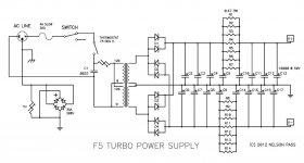
See the PSU schematic of the F5 Turbo article http://www.firstwatt.com/pdf/art_f5_turbo.pdf
Note the bridge + thermistor between audio ground and chassis ground. Also note the thermostat switch.
Last year I had a problem with a transformer shorting to chassis on an Aleph J (or maybe F5?) build that used the PSU design in post #3. The fuse did its job as intended. After diagnosis and repair, all was well.
Attachments
What is the difference in sound with and without those Hammond inductors?
I built these F5 Turbo V3's for a good friend in December, and the inductors were part of the plan from the beginning. So I didn't have the opportunity to listen before and after.
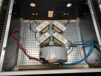
The idea for this build was to go for the best possible sound, and lowest noise. So I started with the boards from the store, and wanted to make a top shelf power supply. I used a snubber circuit after testing the transformers on my quasimodo jig to determine snubber R&C values. I went with a CLC PSU setup to minimize ripple voltage. I went for very tight matching on MOSFETs on the amp boards.
Next step is to get set up to adjust P3 and look at the distortion profile. We want to baseline his old school stereo F5 (without P3) to see the picture, and compare the turbos. Then we'll add sugar to taste on the Turbos. I have the goodies now to do it, but first I have a couple tube amp update projects to knock out before playing around with the distortion analysis.
I also did a CLC setup on 2 SissySIT amps, and they're very quiet on my horn speakers. See the pix. This is a different PSU board - the dual rail decoupled design. I didn't follow ZenMod's dual power supply recipe, but I wanted to get close.
Attachments
That last diagram with the bridge is considered safe, the earlier one that omits it was not, and that is the point I wanted to make clear when I read this:
hi - thank you. The other thing i want to check is that the use of CL60. I am abit nervous about the grounding of this circuit. If something bad happens, would the person touching the chassis be dead long before the circuit with the thermosistor CL60 becomes active?
hi Mooly - is it possible to have a proper video or build guide with the diyaudio PSU board and all the earth connected properly so that all the DIYers can use it as the correct reference? I am surprised that no one has done this. In the official build guide, the board was built using monolithic rectifiers instead of the one used in the universal board sold. The problem with grounding should be highlighted properly in there as well. I am sure there are thousands of F5 out there which have been built without proper grounding and are potentially dangerous.
There is a big difference (different subjects really) between proper audio grounding and grounding for safety.
You asked the question:
and the answer is that if something bad did happen like a primary to secondary short then yes, there is a safety issue. The addition of the high capacity diode bridge is all that is needed to make it acceptable.
In a diy build there is little control over parts used and the mounting and layout of the final build. Any brand of transformer might be used, perhaps some that have had minimal safety testing and approval.
A factory build can if needed specify exact parts to be used such that the risks become very improbable... as in double insulated equipment. It would also specify exact layout and mounting techniques of parts and boards and so on.
None of this is meant to put you off, its all just to keep you safe, specifically as you asked a very valid question.
Add the bridge across the thermistor and you at least stay safe. The bridge has no effect on the audio grounding but does provide a high current path should it be needed in the (admittedly) unlikely event it is called on.
You asked the question:
If something bad happens, would the person touching the chassis be dead long before the circuit with the thermisistor CL60 becomes active?
and the answer is that if something bad did happen like a primary to secondary short then yes, there is a safety issue. The addition of the high capacity diode bridge is all that is needed to make it acceptable.
In a diy build there is little control over parts used and the mounting and layout of the final build. Any brand of transformer might be used, perhaps some that have had minimal safety testing and approval.
A factory build can if needed specify exact parts to be used such that the risks become very improbable... as in double insulated equipment. It would also specify exact layout and mounting techniques of parts and boards and so on.
None of this is meant to put you off, its all just to keep you safe, specifically as you asked a very valid question.
Add the bridge across the thermistor and you at least stay safe. The bridge has no effect on the audio grounding but does provide a high current path should it be needed in the (admittedly) unlikely event it is called on.
- Status
- This old topic is closed. If you want to reopen this topic, contact a moderator using the "Report Post" button.
- Home
- Amplifiers
- Pass Labs
- Some help with FW F5 boards