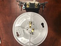
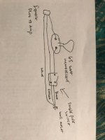
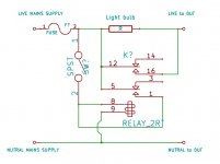
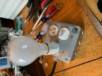
I'm ready to test the PSU with a homemade dim bulb tester. Ive attached a drawing of how I believe I should map the wiring thru a single pole switch and in to a simple bulb socket that will have a 65 watt incandescent bulb in it. I have a three wire sacrificial 15 amp cord I plan to use, cutting the black into and thu the switch. Not sure If I should or need to run the ground thru the switch or not and pls note that the bulb socket does not have a ground screw- only a brass and a silver screw, thru which I am planning to run the single black wire after it exits the single pole switch. If anyone can opine that'd be great! Thanks photos attached of the switch, socket and my drawing of the proposed wiring.
Attachments
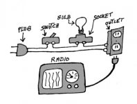
Check for safe operation Build Your Own Current Limiter for Protection when Repairing and Testing Electronic Equipment
Attachments
Pass DIY Addict
Joined 2000
Paid Member
Super handy thing to have. I built one like this: Dim Bulb Tester – Geek-Tips
Another handy tutorial: Compact Dim Bulb Tester Wiring | Audiokarma Home Audio Stereo Discussion Forums
Another handy tutorial: Compact Dim Bulb Tester Wiring | Audiokarma Home Audio Stereo Discussion Forums
 Thanks
A couple of years back (2012) I built a variation of a "dim bulb" tester/supply.
Two 40W bulbs, switchable, in-out, with a variac, and also a +/- 50V DC 5A supply (also variable).
All in one repurposed old Heathkit metal shortwave radio case that I had laying around.
Comes in handy once in a while.
Two 40W bulbs, switchable, in-out, with a variac, and also a +/- 50V DC 5A supply (also variable).
All in one repurposed old Heathkit metal shortwave radio case that I had laying around.
Comes in handy once in a while.
Attachments
Yes switch is only on-off contact on the black ( hot ) wire

This is a really nice and clear diagram.
I added a bypass switch across the lamp as well so that I could take the lamp out of circuit if all is well.
I also mounted the components on a board so I could store it.
Importantly, the components I used were all new external mount items (a mounting box with matching switch plate; a batten mount light holder, an extension cord cut in half etc) rather than trying to repurpose internal mounting components. This allowed me to fully insulate the setup and cost around $10 all up.
...I added a bypass switch across the lamp as well so that I could take the lamp out of circuit if all is well...
If the switch is in the wrong position next time you use it.... A self holding relay would be better.
EDIT. The switch should be a momentary type.
Attachments
Last edited:
If the switch is in the wrong position next time you use it.... A self holding relay would be better.
EDIT. The switch should be a momentary type.
Looks like a bit of overkill for switching out/in a simple current limiting lamp.
I rely on routine and discipline to ensure that doesn't happen.
I always stop and think before finally turning the power switch on to ensure everything is safe and ready to go.
And that's good common sense.
Particularly when working with dangerous voltage or fire threats.
Common Sense...... something it seems is lacking more and more among society.
I suppose that's part of the "Dumbing of Society" that has infiltrated it.
AKA - self-driving, self parking cars.... lane warning alarms.....rear cameras... etc etc...
Pretty soon, you won't need eyes, hands, or a brain, in order to pass a driving test.
Just be a dumb-azzed zombie, living through a smart phone "app".
I FINALLY built one of these a few weeks ago! Would have been handy when a buddy and I tested a TSE with a dead short Line to Neutral! I saw an IEC cord glow blue and it filled the dining room with smoke!
Blue?
One thing that I usually do is to take a meter reading (ohms) across the prongs of the power cord of something suspicious in for service, while working the power switch.
The reading tells me if something's not right beforehand.
Also good practice to ohm-check from power cord to chassis.
Generally, in tech service information/service manuals, the first pages give warnings/info for "leakage" and soundness of such connections.
It's put there for a reason.....
I wish I could find a stash of ES 100 W incandescent lights. Here in the far south everyone has gone CFL and LED crazy. Not that I have a problem with the LEDs mind you, I just stay far away from the CFLs. I fortunately have all the bits and pieces, and a variac.
Kevin
Aren't 50/60 W bulbs available?
Paralleling them is simple.
- Status
- This old topic is closed. If you want to reopen this topic, contact a moderator using the "Report Post" button.
- Home
- Amplifiers
- Pass Labs
- dim bulb tester, "schematic"