Does anyone have a simple cap. multiplier with a lower voltage drop than shown below?
There's the CapMx from Mjohnson and Gtose that can be used with BJTs for a lower voltage drop of 1.3v and up.
Implemented by X.
Prasi made gerbers for it.
I need to make a correction to my notes in post #219:
X1 and X2 are ZVN3310A.
I had been ruminating about which of the cap multipliers to document, and suffered an overwhelming urge to write a post just before bed. Kind of like not having enough coffee.
The cap multiplier shown in the document by J. Hofland is an unusual implementation, which I believe has some weaknesses. This design formed the basis for the one suggested by M. Johnson, and the one eventually used in the SLB power supply. I used a slightly modified version of the SLB in my F6 with success, and the modifications I made were essential to the performance I was eventually able to get from it.
For the SLB, I substituted the MJW1302A for the power transistor Q10, and the KSC2690A for the driver Q9. I used a set of NOS Panasonic FC series 1000 uF caps in the C15 through C18 positions, as the quality of the capacitance being 'multiplied' makes a difference. After some listening to the F6, I finally added KEMET ALS70 series 24,000 uF capacitors to the outputs. These were necessary for energy storage, and make a very noticeable improvement to the sound of my amp. I will also note that the SLB includes a 1N4004 diode from the Collector to Base of the power transistor, as necessary to safely discharge the bulk capacitance on its output during power down.
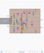
The SLP works pretty well as a ripple eater, but has limited adjustment capability for output voltage. I am currently using another variation in an ongoing MoFo project. One of the things I have found is that the CFP type of capacitance multiplier needs some tuning to be optimized for the particular load it is presented with. The main change I've made to the SLB circuit addresses the limited adjustment capability. I replaced the 200R trimmer resistor with a 1k, and drove the base of the KSC2690A from the wiper terminal of the pot. The RCRC network now consists of 220Ω -> 540 uF -> 220Ω + potentiometer tap -> 470 uF, with a green LED and 10k resistor (recommended for SIT3X) to ground. Implementation is shown below.
This is still a work in progress to get best performance with my MoFo. It is likely that the SIT3X may need slightly different values. I think the Mr Evil version that I wrote about earlier is more general purpose, and won't need much tuning for best performance. That's why I covered it first.
X1 and X2 are ZVN3310A.
I had been ruminating about which of the cap multipliers to document, and suffered an overwhelming urge to write a post just before bed. Kind of like not having enough coffee.
The cap multiplier shown in the document by J. Hofland is an unusual implementation, which I believe has some weaknesses. This design formed the basis for the one suggested by M. Johnson, and the one eventually used in the SLB power supply. I used a slightly modified version of the SLB in my F6 with success, and the modifications I made were essential to the performance I was eventually able to get from it.
For the SLB, I substituted the MJW1302A for the power transistor Q10, and the KSC2690A for the driver Q9. I used a set of NOS Panasonic FC series 1000 uF caps in the C15 through C18 positions, as the quality of the capacitance being 'multiplied' makes a difference. After some listening to the F6, I finally added KEMET ALS70 series 24,000 uF capacitors to the outputs. These were necessary for energy storage, and make a very noticeable improvement to the sound of my amp. I will also note that the SLB includes a 1N4004 diode from the Collector to Base of the power transistor, as necessary to safely discharge the bulk capacitance on its output during power down.
The SLP works pretty well as a ripple eater, but has limited adjustment capability for output voltage. I am currently using another variation in an ongoing MoFo project. One of the things I have found is that the CFP type of capacitance multiplier needs some tuning to be optimized for the particular load it is presented with. The main change I've made to the SLB circuit addresses the limited adjustment capability. I replaced the 200R trimmer resistor with a 1k, and drove the base of the KSC2690A from the wiper terminal of the pot. The RCRC network now consists of 220Ω -> 540 uF -> 220Ω + potentiometer tap -> 470 uF, with a green LED and 10k resistor (recommended for SIT3X) to ground. Implementation is shown below.
This is still a work in progress to get best performance with my MoFo. It is likely that the SIT3X may need slightly different values. I think the Mr Evil version that I wrote about earlier is more general purpose, and won't need much tuning for best performance. That's why I covered it first.
Attachments
Last edited:
Please correct me if my understanding is wrong.
The Tokin is preferable to a MOSFET.
The SIT is used as a source follower, the configuration with the least distortion.
A P FET is used on the bottom half because There isn't a P version of the SIT.
My question is, would a quasi complementary output with 2 SITs be better as a more inherent cancellation method?
I am still trying to understand the harmonic cancellation mechanism. The quasi-comp circuits are sufficiently different that I cannot predict whether the can be cancellation. The FirstWatt F6 topology might be a better candidate, but the transformer distortion would likely dominate after any possible cancellation.Please correct me if my understanding is wrong.
The Tokin is preferable to a MOSFET.
The SIT is used as a source follower, the configuration with the least distortion.
A P FET is used on the bottom half because There isn't a P version of the SIT.
My question is, would a quasi complementary output with 2 SITs be better as a more inherent cancellation method?
The F6 is a different animal than what we have been discussing here. I can say that it certainly responds well to moderate tweaks that take it outside of the original spec. Whether it would be suitable for driving a pair of big depletion mode SITs is somewhat difficult to say. The original used the now unobtainium Papa SITs. Of course the bias scheme would have to be revised.
I suspect more productive results would be to adapt the F6 to some of the more powerful IXYS Mosfets. Best to keep the total gate capacitance and gate charge within a reasonable range. I can recommend the Diamond buffer front end for stronger drive, but this is really a topic for a different thread.")
I suspect more productive results would be to adapt the F6 to some of the more powerful IXYS Mosfets. Best to keep the total gate capacitance and gate charge within a reasonable range. I can recommend the Diamond buffer front end for stronger drive, but this is really a topic for a different thread.
Last edited:
There may not be a good closed form mathematical expression for achieving harmonic cancellation. Instead, there are probably a number of adjacent solutions that will give sonically pleasing results, based on one's preference for harmonic distortion content. H2 relative to H3, H4 and higher order harmonics. The trick is to arrive at a circuit topology that allow some adjustment to the operating points of the output transistors. There may be one set of parameters that is a good all-around solution, but a number of other solutions that work better in one user's system or another.
That's Engineering.
That's Engineering.
...The FirstWatt F6 topology might be a better candidate...
Or maybe some form of PLH F6 hybrid

I have moved further discussion of the SIT3X to a new thread: The SIT-3X Amplifier
 1 image removed from post #223 at members request.
T
...
However, the 2SC4793 and 2SA1837 don't seem to be available anywhere,
....
Some other BJT alternatives for the cascode transistors are:
- MJE253G PNP 100V 15W TO-225
- MJE243G NPN 100V 15W TO-225
- MJE15028G NPN 120V 50W TO-220
- MJE15029G PNP 120V 50W TO-220
- MJE15030G NPN 150V 50W TO-220
- MJE15031G PNP 150V 50W TO-220
Attachments
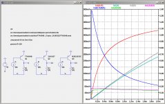
Here are some measurements of real devices by cubicincher:
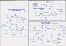
Wayne's BA 2018 linestage
Wayne's BA 2018 linestage
T
...
However, the 2SC4793 and 2SA1837 don't seem to be available anywhere,
....
Some other BJT alternatives for the cascode transistors are:
- MJE253G PNP 100V 15W TO-225
- MJE243G NPN 100V 15W TO-225
- MJE15028G NPN 120V 50W TO-220
- MJE15029G PNP 120V 50W TO-220
- MJE15030G NPN 150V 50W TO-220
- MJE15031G PNP 150V 50W TO-220
...
The 2SK2013 and 2SJ313 might be replaced by he FQP4N20L and FQP3P20, as these seem to work well in the BA-3 pre. Some revision would no doubt be necessary to the bias adjustment.
...
A problem with the FQP3N30 and FQP3P20 might be the higher Vgs of around 5V at 50mA, which results in another 2.7V loss in rail headroom. Maybe no big deal.
I really enjoyed reading through your findings. Great work.
Even though I have build a couple of Nelson's amp, I ended up with quiet a massive tube amplifier chain, all Directly heated with 801a and 300B...still playing around with the last stage.
I am wondering with these nice devices...could I not follow a different path, try it as a 300B/845 replacement ?
So:
- Bias at 400V/100mA (which negative bias would this be at the grid ?) or more current (depends on the OPT, mine is for 100mA)...the PSU is already there....
- So, roughly 40W dissipation, no ?...witha different OPT we could go to 400V/250mA or more...
- rp / internal resistance...not sure where it comes out, but I could anyway have a different OPT wound maybe with 200-300 ohm impedance instead of 3000 for the 300B...that is the only new component I need to get actually.
- fixed bias from the 300B amp (i can generate any voltage you want me to for the 2sk182)
- driven by an Interstage with a 801A tube stage...so if there is any grid current (I believe the SS guys call it gate, no?), the IT has no issue with it as the 801A runs at 20mA...i guess can handle this...and with the much more negative grid/gate voltage, I would expect as well no real issue, not sure if Nelson's 60/600ohm driver impedance suggestion is even still needed then, as the IT with its low Rdc on the secondary of maybe few hundred ohm gives the 2sk182 the ability to breathe gate current away, but hold AC impedance high as there is no 10k resistor gate ground anymore...like a 300B, which has than infinite impedance.
Any fundamental flaws in this idea ?
I still wonder if this will sound actually better than a real tube as the curves do not look as linear as even a 300b or a 814 in triode, but I would be keen to try...if the Pass-SIT are even more linear, it would be even more interesting to see how well a SIT can play when you give it a high quality PSU (no lytics in my HV supply, massive amorphous chokes, 872a rectifiers etc)...which already all there fortunately.
Last edited:
Dear Lynn, I have been re-reading these wonderful posts & thank you again for doing them. Can I ask if you had time to review the suggestion you had made in post 77 ?
The premise sounded most intriguing indeed
"...A potential advantage of this circuit is that the degeneration resistor Rhi can be arbitrarily chosen, independent of the idle bias current and the Rmu gain resistor of the mu-follower. If Rhi has zero resistance, then M1 will behave more like an square-law device and have higher effective transconductance (gme). As Rhi is increased, M1 behaves more linearly and have a lower gme, which can be compensated for by increasing the value of Rmu, such that beta=1+Rmu*gme has the desired value. Is it possible to improve the harmonic structure by carefully choosing Rmu and Rhi?"
That was my thinking also, that there would be an advantage to removing the degeneration of M1. I experimented with it a bit, but did not reach a definitive conclusion. For some reason I saw a significant increase in the noise floor of the output, whose cause I did not resolve.
- Home
- Amplifiers
- Pass Labs
- SIT measurements, Mu Follower, and amplifier build