
I'll put my hand up, I don't mind admitting that I'm a f*ckwhit, I'm sort of lost too (I'm probably speaking for more than a few of us). lhquam, you are far cleverer than me, I can follow what your saying, but you make the assumption that the majority can fill in the blank bits, I'm an idiot; maths isn't my strong point either (they taught it at the school I didn't attend) 
Post 10, Id = A*Vd + B/Rload + C*Vd/Rload + D
What I see is, Id = something x Vd + another something /Rload + a third different something x Vd...........
Post 38 clarified the goal, but not the coefficients; could you name the 4 coefficients [A,B,C,D] please, maybe then the penny would finally drop for this numpty.
Most excellent work by the way
I had the same thought, bought some, tested them, too much drift, 2.037A at switch on (25°C), two hours later, 2.476A @ 66°C. I think I'll be sticking with the opto.
Is that another opto hiding behind the 10,000uF cap between the mystery and unobtainium transistors?
Post 10, Id = A*Vd + B/Rload + C*Vd/Rload + D
What I see is, Id = something x Vd + another something /Rload + a third different something x Vd...........
Post 38 clarified the goal, but not the coefficients; could you name the 4 coefficients [A,B,C,D] please, maybe then the penny would finally drop for this numpty.
Most excellent work by the way
...I really like the IXYS depletion mode N-channel parts. I wish they offered them in a TO227 hockey puck. That package would be perfect for a Mu follower Tokin SIT build.
I had the same thought, bought some, tested them, too much drift, 2.037A at switch on (25°C), two hours later, 2.476A @ 66°C. I think I'll be sticking with the opto.
New DIY Sony channel finally seeing the light.

Is that another opto hiding behind the 10,000uF cap between the mystery and unobtainium transistors?
...........
Is that another opto hiding behind the 10,000uF cap between the mystery and unobtainium transistors?
Hawk eyes!
:--))
I would say yes!
...
Post 10, Id = A*Vd + B/Rload + C*Vd/Rload + D
What I see is, Id = something x Vd + another something /Rload + a third different something x Vd...........
Post 38 clarified the goal, but not the coefficients; could you name the 4 coefficients [A,B,C,D] please, maybe then the penny would finally drop for this numpty.
...
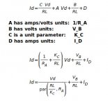
I would also like to understand any physical meaning for the A, B, C, D parameters of the sweet-spot surface, but thus far I have not found any. It is possible to assign physical units however, as shown below. (The notation par(RL/K_C,R_A) is a parallel resistance.)
Attachments
Are you sure that the 6-pin DIP on the left is an opto? The 6-pin optos provide a pin connecting to the phototransistor base, but I have never seen Nelson use that connection.Hawk eyes!
:--))
I would say yes!


I would also like to understand any physical meaning for the A, B, C, D parameters of the sweet-spot surface, but thus far I have not found any. It is possible to assign physical units however, as shown below. (The notation par(RL/K_C,R_A) is a parallel resistance.)
Thank you, I will try to assimilate
Are you sure that the 6-pin DIP on the left is an opto? The 6-pin optos provide a pin connecting to the phototransistor base, but I have never seen Nelson use that connection.
I can't read the top of it, so not sure of anything; from what I can see, it looks like pin 6 is not connected, I suppose we'll find out soon enough.
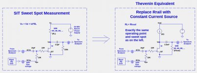
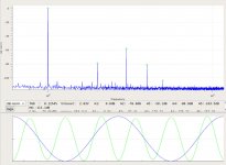
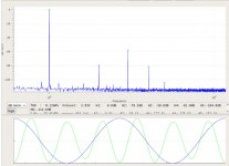
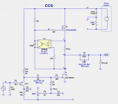
The image below shows the SIT sweet-spot bench-test circuit on the left converted to a Thevenin equivalent circuit using a constant current source. The sweet spot is unchanged, using the same values for Id, Vd, and Rload, as shown in the spectra for the two circuits. The spectra the for the bench-test and CCS circuits respectively.
The complete circuit for the CCS is shown in the 4th image.
The complete circuit for the CCS is shown in the 4th image.
Attachments
A single parameter characterizes the "Sweet Spot" of a SIT
Amazing result: One parameter characterizes the "Sweet Spot" of a SIT
The 'Sweet Spot" surface shown in post #10 has four parameters (A, B, C, and D). In post #44 I attached physical units to those parameters:
Id=(C*Vd)/RL+A*Vd+B/RL+D;
A has amps/volts units: 1/R_A
B has volts units: V_B
C is a unit parameter: K_C
D has amps units: I_D
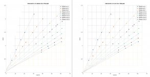
Yesterday I extended the range of of values for the load resistor RL to include 4R, 6R, 8R, 10R, 12R, 14R, 16R, and 18R values. After looking at the plots I wondered what would happen if I eliminated the B and D parameters, which has the effect of forcing the lines of constant RL to intersect the points Vd=0, Id=0, RL, as shown in the first image below. On the left are are select of lines of the form Id=a*Vd+b, whereas on the right the lines are Id=c*Vd, where the values of a,b,c depend on RL.
I went one step further and eliminated the A parameter, resulting in the equation Id = C*Vd/RL. Here is a summary of the RMS errors of the residual fit errors for the three solutions:
RMS = 0.018A of 4 parameter [A,B,C,D] fit Id = C*Vd/RL+A*Vd+B/RL+D
RMS = 0.031A of 2 parameter ___[A,C] fit Id = C*Vd/RL+A*Vd
RMS = 0.069A of 1 parameter _____[C] fit Id = C*Vd/RL
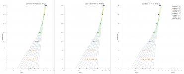
The 2nd image contains 3 plots showing the sweet spot surfaces in an orientation similar to that of post #10.
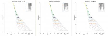
The 3rd image contains 3 plots showing the sweet spot surfaces in an orientation similar to that of post #10.
In the rightmost plots, showing the 1-parameter surface fit, the error become visible for the lines with the highest RL values.
Thus, the "Sweet Spot" equations Id = C*Vd/RL and Vd = Id*RL/C are good 1st order approximations.
Who would have guessed that a single parameter could characterize the "Sweet Spot" of a SIT?
Amazing result: One parameter characterizes the "Sweet Spot" of a SIT
The 'Sweet Spot" surface shown in post #10 has four parameters (A, B, C, and D). In post #44 I attached physical units to those parameters:
Id=(C*Vd)/RL+A*Vd+B/RL+D;
A has amps/volts units: 1/R_A
B has volts units: V_B
C is a unit parameter: K_C
D has amps units: I_D
Yesterday I extended the range of of values for the load resistor RL to include 4R, 6R, 8R, 10R, 12R, 14R, 16R, and 18R values. After looking at the plots I wondered what would happen if I eliminated the B and D parameters, which has the effect of forcing the lines of constant RL to intersect the points Vd=0, Id=0, RL, as shown in the first image below. On the left are are select of lines of the form Id=a*Vd+b, whereas on the right the lines are Id=c*Vd, where the values of a,b,c depend on RL.
I went one step further and eliminated the A parameter, resulting in the equation Id = C*Vd/RL. Here is a summary of the RMS errors of the residual fit errors for the three solutions:
RMS = 0.018A of 4 parameter [A,B,C,D] fit Id = C*Vd/RL+A*Vd+B/RL+D
RMS = 0.031A of 2 parameter ___[A,C] fit Id = C*Vd/RL+A*Vd
RMS = 0.069A of 1 parameter _____[C] fit Id = C*Vd/RL
The 2nd image contains 3 plots showing the sweet spot surfaces in an orientation similar to that of post #10.
The 3rd image contains 3 plots showing the sweet spot surfaces in an orientation similar to that of post #10.
In the rightmost plots, showing the 1-parameter surface fit, the error become visible for the lines with the highest RL values.
Thus, the "Sweet Spot" equations Id = C*Vd/RL and Vd = Id*RL/C are good 1st order approximations.
Who would have guessed that a single parameter could characterize the "Sweet Spot" of a SIT?
Attachments
so , how to read them, in most precise way ?
I think you would need a 3D image!
I was looking at the graphs last night and thought... some of the parameters will be more or less fixed, nominal load Z, the power requirements would determine the supply voltage.
This is the bit I wondered about, if the device was characterised with a transistor analyser, and the results loaded into a spread sheet; then, input the required load impedance and Vd (which would probably be V/2 for maximum swing), apply the formula and hit enter, and out pops Id for the sweet spot.
Choosing Vrail (the rail voltage) and Id (the idle bias current) is not a trivial exercise. Here are some considerations:
- Choose a power dissipation based on the heatsinks and packaging approach you intend to use. The typical FirstWatt stereo amplifier dissipates about 150W per heatsink. This determines Total_Watts = Id * Vrail.
- For maximum class-A power output, one would like to maximize Id subject to the constraint than Vrail= Total_Watts/Id is sufficiently large that the amplifier does not leave class-A at its maximum power output.
- In a push-pull amplifier, ideally Vrail = 2*Vd in order to maximize class-A amplifier power output. A SIT-1, single ended topology is totally different in that regard.
- Use the Sweet-Spot equation to estimate Vd = Id*RL/C. RL depends on both Rload (the speaker load) and the amplifier topology. In the mu-follower RL=(PPR+1)*Rload+Rmu. I have not yet presented the mu-follower equations, but here is an important mu-follower relationship: RL=(PPR+1)*Rload+Rmu, where PPR is the push-pull ratio; the ratio of the AC current from the mu-follower FET to the AC current from the SIT. For approximation purposes, Rmu can be ignored.

lhquam,you could dance rings round me all day with this stuff.
I'm familiar with the usual bias process, crank it till it catches fire, then back it off a bit.
I know this thread is based around single ended topology, and adjusting Vd is simple; but if applying it to push pull, the supply rails would need to be variable to adjust Vd, that's not as easy or convenient, which is why I was thinking that adjusting Id would be the easier approach.
The typical FirstWatt stereo amplifier dissipates about 150W per heatsink.
Wouldn't that be 75W per heatsink, left and right, for a total of 150W for both?
lhquam,you could dance rings round me all day with this stuff.
I'm familiar with the usual bias process, crank it till it catches fire, then back it off a bit.
I know this thread is based around single ended topology, and adjusting Vd is simple; but if applying it to push pull, the supply rails would need to be variable to adjust Vd, that's not as easy or convenient, which is why I was thinking that adjusting Id would be the easier approach.
My mu-follower push-pull information is about ready to post. Unfortunately it is full of math, but I will (eventually) use my the amplifier channels as an example of the math equations.
- Home
- Amplifiers
- Pass Labs
- SIT measurements, Mu Follower, and amplifier build