I'm contemplating building an Aleph J (or BA-3 - can't decide), and I'm looking to maximize heatsink area for a given footprint.
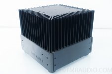
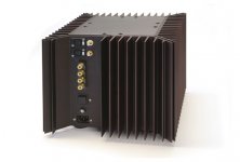
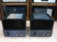
I'm looking at the Aleph 0 case design for inspiration (attached). Four identical heatsinks, one on each face, makes for easy construction compared to the later Aleph models with the different heatsink on the rear containing the inputs (attached). I'm considering four of the 5U/300mm Dissipante heatsinks.
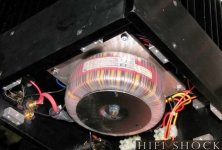
However, since the inputs on the Aleph 0 are pushed to the bottom of the casing (attached), which is where the transformer is located, the input signal wiring is very close to the transformer (attached). In contrast, the traditional Dissipante layout puts the transformer relatively far away from the input wiring (attached).
Would the Aleph 0 layout result in unnecessary amounts of noise? Is the additional footprint worthwhile? I'd also have to scale back the heatsinking to the normal 4x 5U/200mm - certainly doable, but I'd like heatsink temps as low as possible.
I'm looking at the Aleph 0 case design for inspiration (attached). Four identical heatsinks, one on each face, makes for easy construction compared to the later Aleph models with the different heatsink on the rear containing the inputs (attached). I'm considering four of the 5U/300mm Dissipante heatsinks.
However, since the inputs on the Aleph 0 are pushed to the bottom of the casing (attached), which is where the transformer is located, the input signal wiring is very close to the transformer (attached). In contrast, the traditional Dissipante layout puts the transformer relatively far away from the input wiring (attached).
Would the Aleph 0 layout result in unnecessary amounts of noise? Is the additional footprint worthwhile? I'd also have to scale back the heatsinking to the normal 4x 5U/200mm - certainly doable, but I'd like heatsink temps as low as possible.
Attachments
I was initially interested in those heatsinks as well, but the price was way too high to make building a pair of monoblocks an attractive option.
Regarding the proximity of the circuitry to the power transformer – the aleph amplifier circuit is relatively insensitive to picking up electromagnetic feilds. No signal transformer, such as used in the M2 or F6.
Regarding the proximity of the circuitry to the power transformer – the aleph amplifier circuit is relatively insensitive to picking up electromagnetic feilds. No signal transformer, such as used in the M2 or F6.
Progress
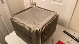
Found some salvage heatsinks on eBay - approx. 9" x 12" each with a 1/2" thick heat spreader/base. This thing sure is heavy.
Bottom panels are 3.5" high. The rear panel will have all inputs/outputs. I'm debating whether to run a power switch to the front panel - I'd like to keep AC lines short, but it would be convenient.
At this point, the plan is to mount two output devices on each sink and run each device at about 30 W - temps should be reasonably low. I'm wondering if the thing is bolted together well enough so that the base (1/8" aluminum) could dissipate the 25-35 W for a dual-mono 30mF-CapMx-30mF PSU. I'm planning on using thermal compound for final assembly.
If I can't mount the pass transistors on the base, I'll have to run leads up to the main heatsinks. In view of this, I shrunk the Gtose CapMx to fit right on the leads of the transistor, so the only "flying leads" I'd need would be the output of the first cap bank, the input of the second cap bank, and a line back to ground.
It's this line back to ground that concerns me. Would it go back to the star? to the capacitors?
Attachments

Last edited:
Progess
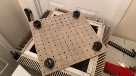
Pictures, in order:
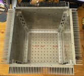
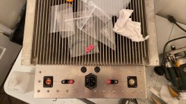
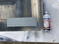
1. Back panel cut and drilled
2. Top perforated sheet fitted
3. Baseplate drilled and feet attached
4. Toroids (2 Antek AS-4222) mounted and cute face installed on the underside of the internal ledge. This is the chassis upside down - compare to pictures in previous post.
5. Second angle showing ledge
If the space looks tight in the pictures, it's because my guest bathroom is my apartment's best approximation of a workshop.
Pictures, in order:
1. Back panel cut and drilled
2. Top perforated sheet fitted
3. Baseplate drilled and feet attached
4. Toroids (2 Antek AS-4222) mounted and cute face installed on the underside of the internal ledge. This is the chassis upside down - compare to pictures in previous post.
5. Second angle showing ledge
If the space looks tight in the pictures, it's because my guest bathroom is my apartment's best approximation of a workshop.
Attachments
Last edited:
 title changed as requested.
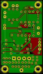
After realizing that $10 in plated perfboard from Amazon was a lot cheaper than $100 of custom PCBs that may or may not work as a first-time design (and would be delivered a lot sooner), I switched from my original plans for a slick SMD construction (see Babelfish J thread here) to tried-and-true through hole components, and I'll be laying out the motherboard about the same as shown (except P2P instead of a PCB, of course). The CapMx and PSU will also be P2P on perfboard.
Since I'm keeping it simple, I'm no longer cascoding the input pair (for now - I did toss a few extra transistors in my Mouser cart, so we'll see what happens to those), and I'm keeping the voltage at about 25 V after the CapMx. With the generous heatsinking, I think I'll shoot for about 2.5 A total bias.
I haven't even hit the halfway point of this build and I'm already thinking about how this chassis and PSU would be perfect for a BBA-3. This hobby is a slippery slope!
Attachments
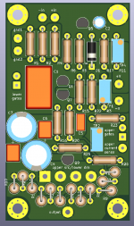
Super compact layout and very nice looking case! What footprint are you using for the power resistors? I can't tell based on scale of the caps but based on the size of the pots, it doesn't look like the footprint is big enough for the power resistors.
Is the numbering associated with any specific schematic posted somewhere?
Along those lines of thought - keep in mind that you will have to get meter clips on some of those resistor legs to adjust this thing (bias/offset). A nice compact layout is better only so far as it gets you into the case but once the lid is on, nobody knows how small you shrunk it.
Oh, wait a minute, are all the power resistors at the bottom of the board in vertical positions? Maybe you are fine for spacing but still keep in mind adjustment so you'll need to be able to attach to an electrical equivalent if you cannot get under one of those resistors to measure Iq.
The compact layout grew from my desire to get a PCB from OSHPARK as cheaply as possible. Now it's basically the limitation of the cheap variety pack of perfboard I got from Amazon - the one I'm considering is 7 cm by 9 cm, whereas the PCB above is about 5 cm by 9 cm.
4.5 mm diameter with 5 mm pitch (vertical).
These are the current sense resistors for the active current source, so they will see high current only on high output peaks. Additionally, there are 12 1W 1 Ohm resistors in parallel, so each one will only see a small amount of current. The selection of these resistors was driven by my choice that each MOSFET will have 3 1W 1 Ohm resistors on the source - cheapest way to get 1% thin film source resistors.
The source resistors will be mounted on the PCBs with the output IRFP240s with much more breathing room.
No, I haven't lined it up with the published schematics, mainly because it doesn't exactly map onto the published schematics, but also because I was lazy.
What footprint are you using for the power resistors?
4.5 mm diameter with 5 mm pitch (vertical).
These are the current sense resistors for the active current source, so they will see high current only on high output peaks. Additionally, there are 12 1W 1 Ohm resistors in parallel, so each one will only see a small amount of current. The selection of these resistors was driven by my choice that each MOSFET will have 3 1W 1 Ohm resistors on the source - cheapest way to get 1% thin film source resistors.
The source resistors will be mounted on the PCBs with the output IRFP240s with much more breathing room.
Is the numbering associated with any specific schematic posted somewhere?
No, I haven't lined it up with the published schematics, mainly because it doesn't exactly map onto the published schematics, but also because I was lazy.
Last edited:
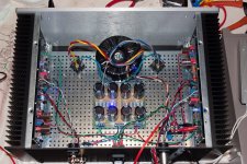
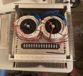
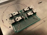
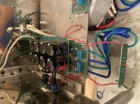
rectifier for one channel
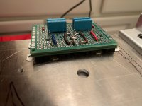
I forgot how tedious P2P wiring was.
This little unit contains 8 FERD units for one channel's PSU as well as the quasimodo snubber components for an Antek 4222 (the results thread is VERY helpful. It'll sit on the ledge within the unit on the opposite side from the transformers - you can see the transformer bolt hole in the first picture.
I stacked the perfboard three layers thick to better distribute the clamping pressure from the three screws (only one pictured) onto the diode bodies.
I'll solder the transformer secondaries into the perfboard during final assembly. I don't have any crimping tools, so I'm making the most of my $5 iron.
Attachments

paint
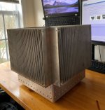
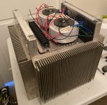
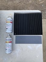
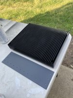
After trying to treat the heatsinks with phosphoric acid (naval jelly) to get an even matte oxidized finish - which didn't do nearly as much as I hoped - I decided that I had to buckle down and do some painting. I hate painting. However, I hate painting less than I am wary of buying highly caustic chemicals to anodize at home, so paint it is.
I thought long and hard about painting the heatsinks. There are many threads here debating the wisdom of doing so. The conflict boils down to whether the improvement to radiation heat transfer outweighs the impingement on conductive/convective heat transfer.
This article says paint is good (paper is attached). For a steam radiator which operates with 70% convection and 30% radiation, "we may expect to gain 10 to 15 per cent in heat dissipation into the room by covering the ordinary multisegmented house radiator with a nonmetallic paint." (p. 187)
Per Wakefield-Vette, that's how our kind of heatsinks typically dissipate - 70% convection and 30% radiation. See p. 7 of this paper. (also attached)
The paint layer is very thin - it does not appreciably change the geometry of the heatsink. Since natural convection is driven largely by the geometry of the sink, that portion of the equation won't appreciably change. However, the temperature differential between the heatsink and ambient drives the convective process.
A layer of paint will add some thermal resistance to the outside of the heatsink. For a given heat passing through the sink, the metal temperature will be higher than the surface temperature (i.e., paint temperature). However, for a given heat output, the surface temperature will remain the same (assuming no influence of radiation), so again, the convective process remains the same. Heat lost from the paint will lower the surface temperature, hampering the convective process, but that's a good thing, since heat lost is heat lost.
So the question remains - how much will the temperature change in the metal?
If the heat from the metal sink to the surface is
q = (T_metal - T_paint) / (R_metal-paint),
we have
(T_metal - T_paint) = q * (paint thickness) / (paint area * thermal conductivity of paint).
For acrylic paint, thermal conductivity is about 1 W/mK. See this paper. (also attached)
Let's say paint thickness after spraying and drying will be around 0.1-0.2 mm.
for a 50 W sink with width = 300 mm, length_fin = 30 mm, height = 200, num_fin = 20 fins, we get a 0.03 deg C rise.
Considering the change in emissivity from 0.04 to 0.9x, there are HUGE gains to be had for the 30% radiation of our heat transfer and only negligible losses to be had in the remaining 70%.
Attachments
Looking good!
Here's my perfboard version of an Aleph: Pictures of your diy Pass amplifier
Perfboard always seems like a good idea at first, and when you're halfway into the build you realize it's a PITA. The trick is to not think about, take a deep breath, and just go on...
Here's my perfboard version of an Aleph: Pictures of your diy Pass amplifier
Perfboard always seems like a good idea at first, and when you're halfway into the build you realize it's a PITA. The trick is to not think about, take a deep breath, and just go on...
I'm contemplating building an Aleph J (or BA-3 - can't decide), and I'm looking to maximize heatsink area for a given footprint.
I'm looking at the Aleph 0 case design for inspiration (attached). Four identical heatsinks, one on each face, makes for easy construction compared to the later Aleph models with the different heatsink on the rear containing the inputs (attached). I'm considering four of the 5U/300mm Dissipante heatsinks.
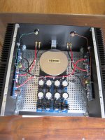
I suppose you should try to place the mains transformer as close as possible to a mains voltage point of entry. This will help in reducing the internal mains voltage wiring (it can be really short, like 5-6cm only).
The other thing to pay attention to, whilst thinking about the layout, is the short DC supply wiring. This can also be achieved if you correctly place the PS board.
The secondary windings' wires are tucked underneath the PS board.
Have a look at the attached photo. This was the original incarnation.... since then, I removed the 1uF capacitors and played a bit with internal wiring
Attachments
Attachments
- Status
- This old topic is closed. If you want to reopen this topic, contact a moderator using the "Report Post" button.
- Home
- Amplifiers
- Pass Labs
- Aleph 0 layout for Aleph J